instrument panel AUDI A4 1997 B5 / 1.G AC System Electrical Testing Workshop Manual
[x] Cancel search | Manufacturer: AUDI, Model Year: 1997, Model line: A4, Model: AUDI A4 1997 B5 / 1.GPages: 47, PDF Size: 0.16 MB
Page 10 of 47

01-122
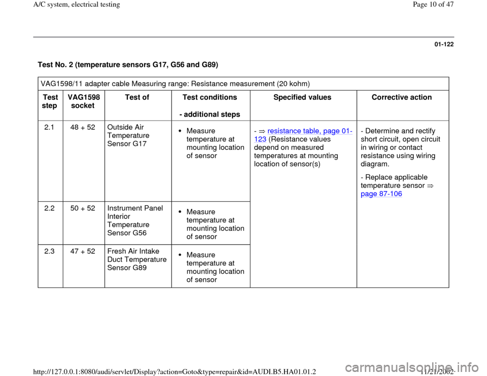
Test No. 2 (temperature sensors G17, G56 and G89) VAG1598/11 adapter cable Measuring range: Resistance measurement (20 kohm)
Test
step VAG1598
socket Test of
Test conditions
- additional steps Specified values
Corrective action
2.1 48 + 52 Outside Air
Temperature
Sensor G17
Measure
temperature at
mounting location
of sensor - resistance table, page 01
-
123
(Resistance values
depend on measured
temperatures at mounting
location of sensor(s)
- Determine and rectify
short circuit, open circuit
in wiring or contact
resistance using wiring
diagram.
- Replace applicable
temperature sensor
page 87
-106
2.2 50 + 52 Instrument Panel
Interior
Temperature
Sensor G56
Measure
temperature at
mounting location
of sensor
2.3 47 + 52 Fresh Air Intake
Duct Temperature
Sensor G89 Measure
temperature at
mounting location
of sensor
Pa
ge 10 of 47 A/C s
ystem, electrical testin
g
11/21/2002 htt
p://127.0.0.1:8080/audi/servlet/Dis
play?action=Goto&t
yp
e=re
pair&id=AUDI.B5.HA01.01.2
Page 11 of 47

01-123
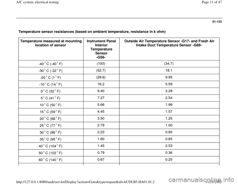
Temperature sensor resistances (based on ambient temperature, resistance in k ohm) Temperature measured at mounting
location of sensor Instrument Panel
Interior
Temperature
Sensor
-G56- Outside Air Temperature Sensor -G17- and Fresh Air
Intake Duct Temperature Sensor -G89-
-40 C (-40 F)
(100) (34.7)
-30 C (-22 F) (52.7) 18.1
-20 C (1 F) (28.6) 9.95
-10 C (14 F) 16.2 5.59
0 C (32 F) 9.40 3.28
5 C (41 F) 7.27 2.54
10 C (50 F) 5.66 1.99
15 C (59 F) 4.45 1.57
20 C (68 F) 3.50 1.25
25 C (77 F) 2.79 1.00
30 C (86 F) 2.23 0.80
35 C (95 F) 1.80 0.65
40 C (104 F) 1.45 0.53
50 C (122 F) 0.79 0.36
60 C (140 F) 0.67 0.25
Pa
ge 11 of 47 A/C s
ystem, electrical testin
g
11/21/2002 htt
p://127.0.0.1:8080/audi/servlet/Dis
play?action=Goto&t
yp
e=re
pair&id=AUDI.B5.HA01.01.2
Page 39 of 47

01-147
Notes:
The following test steps are only performed for A/C control heads -E87- with two displays:
Teststep 2.2 (the instrument panel interior temperature sensor -G56- is installed in A/C control heads -E87- with one
display)
Test step 5.7 (the interior temperature sensor fan -V42- is installed in A/C control heads -E87- with one display)
Switch on test area at VAG1526 multimeter: voltage test (20 V =)
VAG1598/11 adapter cable connected
Test
step VAG1598A
socket Test of
Test
requirements
- additional
operations Specified
value Corrective action
1.15
4) 46 + Ground
3) Power supply
terminal 58 of A/C
control head -E87-
Ignition
switched on Park light
switched on
approx.
battery
voltage - Locate and repair open circuit or short
circuit to Ground in wiring connection to
A/C control head -E87- using wiring
diagram
1.16
4) 46 + Ground
3) Power supply
terminal 58 of A/C
control head -E87-
Ignition
switched on Park light
- Locate and repair open circuit or short
circuit to Ground in wiring connection to
A/C control head -E87- using wiring
diagram.
Pa
ge 39 of 47 A/C s
ystem, electrical testin
g
11/21/2002 htt
p://127.0.0.1:8080/audi/servlet/Dis
play?action=Goto&t
yp
e=re
pair&id=AUDI.B5.HA01.01.2