ECO mode AUDI A4 1997 B5 / 1.G AEB Engine OBD and DTC
[x] Cancel search | Manufacturer: AUDI, Model Year: 1997, Model line: A4, Model: AUDI A4 1997 B5 / 1.GPages: 57, PDF Size: 0.2 MB
Page 10 of 57

01-6
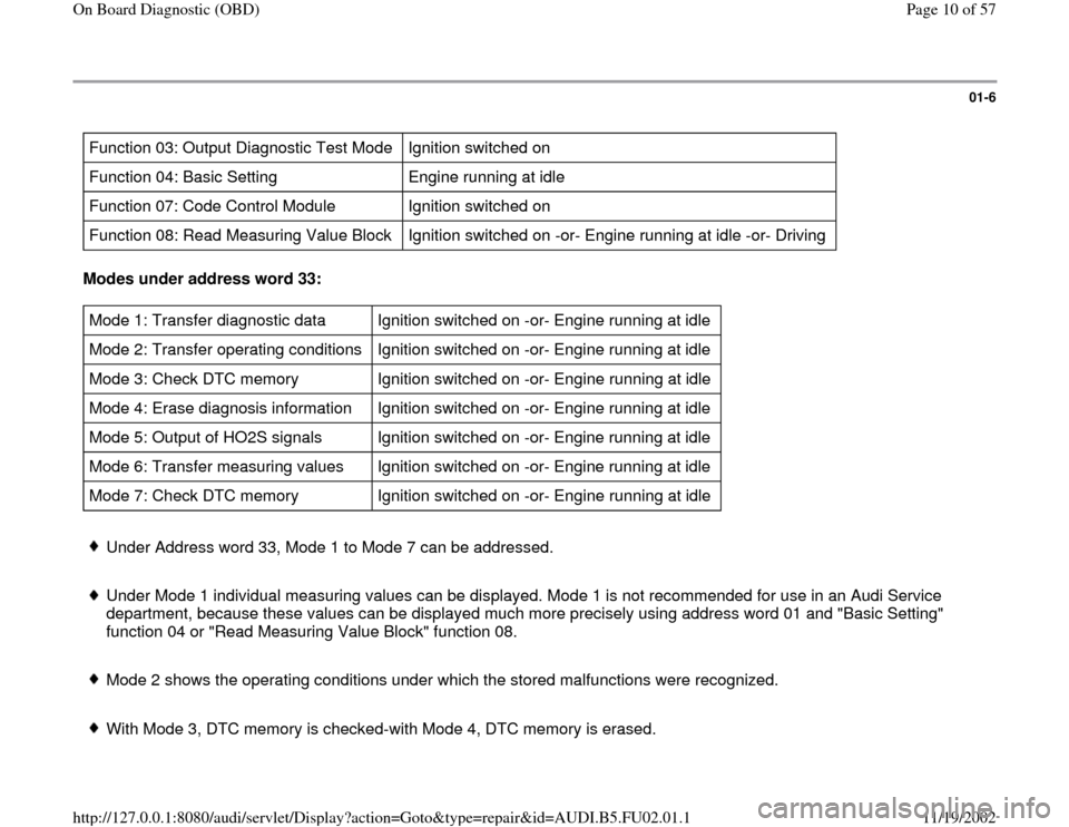
Function 03: Output Diagnostic Test Mode Ignition switched on
Function 04: Basic Setting Engine running at idle
Function 07: Code Control Module Ignition switched on
Function 08: Read Measuring Value Block Ignition switched on -or- Engine running at idle -or- Driving Modes under address word 33: Mode 1: Transfer diagnostic data Ignition switched on -or- Engine running at idle
Mode 2: Transfer operating conditions Ignition switched on -or- Engine running at idle
Mode 3: Check DTC memory Ignition switched on -or- Engine running at idle
Mode 4: Erase diagnosis information Ignition switched on -or- Engine running at idle
Mode 5: Output of HO2S signals Ignition switched on -or- Engine running at idle
Mode 6: Transfer measuring values Ignition switched on -or- Engine running at idle
Mode 7: Check DTC memory Ignition switched on -or- Engine running at idle Under Address word 33, Mode 1 to Mode 7 can be addressed.
Under Mode 1 individual measuring values can be displayed. Mode 1 is not recommended for use in an Audi Service
department, because these values can be displayed much more precisely using address word 01 and "Basic Setting"
function 04 or "Read Measuring Value Block" function 08.
Mode 2 shows the operating conditions under which the stored malfunctions were recognized.
With Mode 3, DTC memory is checked-with Mode 4, DTC memory is erased.
Pa
ge 10 of 57 On Board Dia
gnostic
(OBD
)
11/19/2002 htt
p://127.0.0.1:8080/audi/servlet/Dis
play?action=Goto&t
yp
e=re
pair&id=AUDI.B5.FU02.01.1
Page 11 of 57

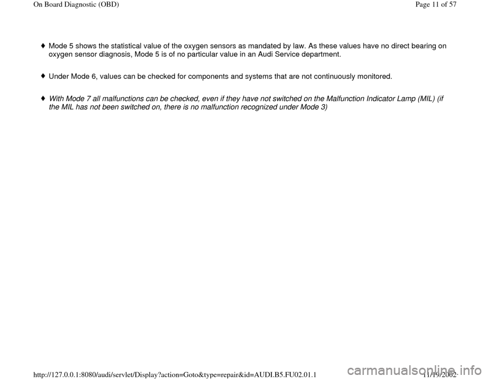
Mode 5 shows the statistical value of the oxygen sensors as mandated by law. As these values have no direct bearing on
oxygen sensor diagnosis, Mode 5 is of no particular value in an Audi Service department.
Under Mode 6, values can be checked for components and systems that are not continuously monitored.
With Mode 7 all malfunctions can be checked, even if they have not switched on the Malfunction Indicator Lamp (MIL) (if
the MIL has not been switched on, there is no malfunction recognized under Mode 3)
Pa
ge 11 of 57 On Board Dia
gnostic
(OBD
)
11/19/2002 htt
p://127.0.0.1:8080/audi/servlet/Dis
play?action=Goto&t
yp
e=re
pair&id=AUDI.B5.FU02.01.1
Page 14 of 57

01-8
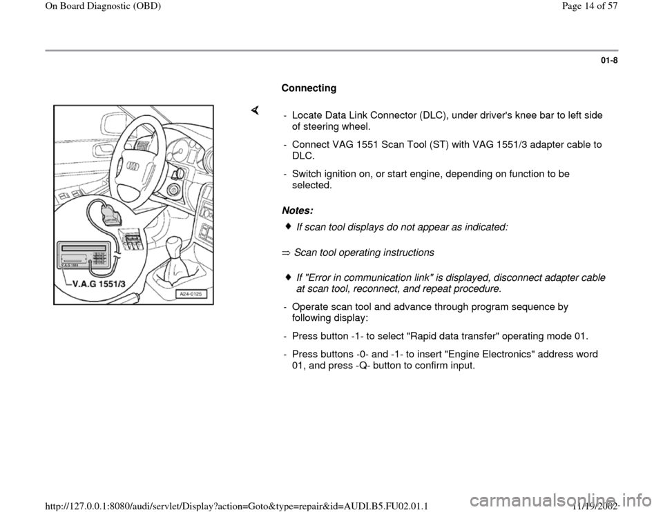
Connecting
Notes:
Scan tool operating instructions - Locate Data Link Connector (DLC), under driver's knee bar to left side
of steering wheel.
- Connect VAG 1551 Scan Tool (ST) with VAG 1551/3 adapter cable to
DLC.
- Switch ignition on, or start engine, depending on function to be
selected.
If scan tool displays do not appear as indicated:If "Error in communication link" is displayed, disconnect adapter cable
at scan tool, reconnect, and repeat procedure.
- Operate scan tool and advance through program sequence by
following display:
- Press button -1- to select "Rapid data transfer" operating mode 01.
- Press buttons -0- and -1- to insert "Engine Electronics" address word
01, and press -Q- button to confirm input.
Pa
ge 14 of 57 On Board Dia
gnostic
(OBD
)
11/19/2002 htt
p://127.0.0.1:8080/audi/servlet/Dis
play?action=Goto&t
yp
e=re
pair&id=AUDI.B5.FU02.01.1