engine AUDI A4 1997 B5 / 1.G AFC Engine Fuel Supply System Components Workshop Manual
[x] Cancel search | Manufacturer: AUDI, Model Year: 1997, Model line: A4, Model: AUDI A4 1997 B5 / 1.GPages: 24, PDF Size: 0.22 MB
Page 4 of 24

20-3
Safety precautions
WARNING!
When removing and installing the fuel pump
or fuel level sensor from a filled or partially
filled fuel tank:
BEFORE beginning repairs, the suction pipe
of an exhaust extraction system must be
located near the fuel tank opening so that
escaping fuel vapors can be immediately
carried away.
If no exhaust extraction system is available,
a radial fan (motor located outside airflow)
with volume of at least 15 m3/hr (9 cfm) may
be used.
Wear fuel-resistant gloves whenever working
with open parts of the fuel system.
Be sure the ignition is switched OFF, when:
Disconnecting fuel injection system wiring
Connecting or disconnecting test equipment
leads
BEFORE cranking the engine at starting RPM
Pa
ge 4 of 24 Fuel su
pp
ly system com
ponents, removin
g and installin
g
11/21/2002 htt
p://127.0.0.1:8080/audi/servlet/Dis
play?action=Goto&t
yp
e=re
pair&id=AUDI.B5.GE01.20.1
Page 6 of 24

20-4
CAUTION!
BEFORE disconnecting the battery:
Stop the engine.
Be sure the ignition is switched OFF (also
applies when connecting the battery). Failure
to do so may damage the Engine Control
Module (ECM).
Be sure of the proper radio code (for vehicles
equipped with coded anti-theft radio).
Be sure the battery negative (-) cable is
disconnected, when:
Working on the electrical system
Resistance (spot) welding or electric arc
welding anywhere on the vehicle.
When connecting and disconnecting
electrical test equipment (LED voltage tester,
multimeter, etc.):
Be sure the ignition is switched OFF.
Use correct adapters from the VW 1594
Pa
ge 6 of 24 Fuel su
pp
ly system com
ponents, removin
g and installin
g
11/21/2002 htt
p://127.0.0.1:8080/audi/servlet/Dis
play?action=Goto&t
yp
e=re
pair&id=AUDI.B5.GE01.20.1
Page 19 of 24

20-12
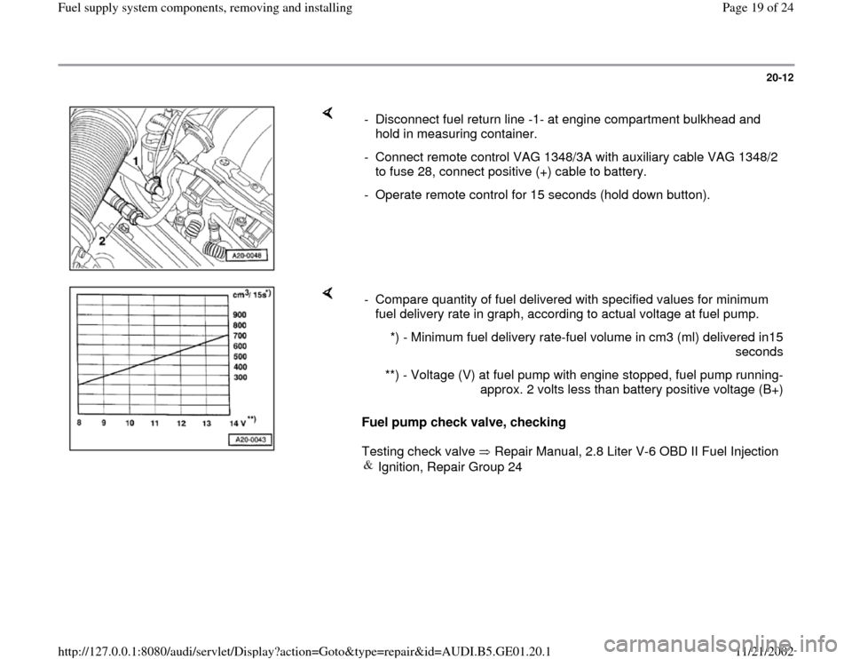
- Disconnect fuel return line -1- at engine compartment bulkhead and
hold in measuring container.
- Connect remote control VAG 1348/3A with auxiliary cable VAG 1348/2
to fuse 28, connect positive (+) cable to battery.
- Operate remote control for 15 seconds (hold down button).
Fuel pump check valve, checking
Testing check valve Repair Manual, 2.8 Liter V-6 OBD II Fuel Injection
Ignition, Repair Group 24 - Compare quantity of fuel delivered with specified values for minimum
fuel delivery rate in graph, according to actual voltage at fuel pump.
*) - Minimum fuel delivery rate-fuel volume in cm3 (ml) delivered in15
seconds
**) - Voltage (V) at fuel pump with engine stopped, fuel pump running-
approx. 2 volts less than battery positive voltage (B+)
Pa
ge 19 of 24 Fuel su
pp
ly system com
ponents, removin
g and installin
g
11/21/2002 htt
p://127.0.0.1:8080/audi/servlet/Dis
play?action=Goto&t
yp
e=re
pair&id=AUDI.B5.GE01.20.1
Page 21 of 24

20-14
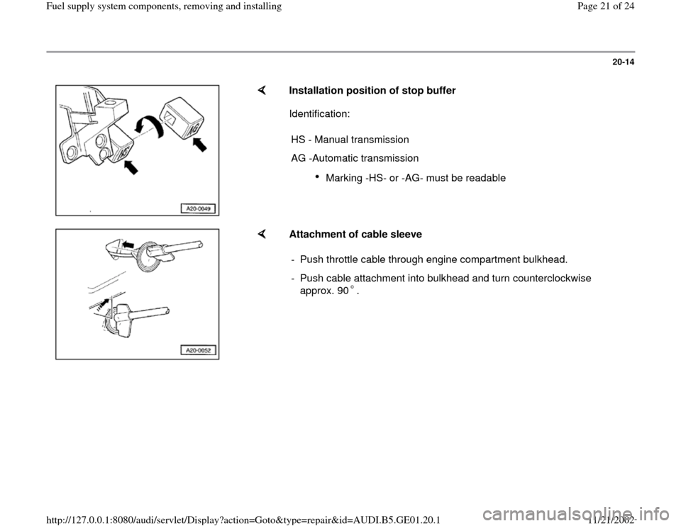
Installation position of stop buffer
Identification:
HS - Manual transmission
AG -Automatic transmission
Marking -HS- or -AG- must be readable
Attachment of cable sleeve
- Push throttle cable through engine compartment bulkhead.
- Push cable attachment into bulkhead and turn counterclockwise
approx. 90 .
Pa
ge 21 of 24 Fuel su
pp
ly system com
ponents, removin
g and installin
g
11/21/2002 htt
p://127.0.0.1:8080/audi/servlet/Dis
play?action=Goto&t
yp
e=re
pair&id=AUDI.B5.GE01.20.1