sensor AUDI A4 1997 B5 / 1.G AFC Engine On Board Diagnostic Multiport Fuel Injection Workshop Manual
[x] Cancel search | Manufacturer: AUDI, Model Year: 1997, Model line: A4, Model: AUDI A4 1997 B5 / 1.GPages: 366, PDF Size: 1.21 MB
Page 279 of 366

01-198
Display groups 015 and 016
Notes on display fields 2, 3 and 4:
If there is a difference of more than a factor of 3 between the lowest and the highest knock sensor signal in one display group,
the following malfunction is possible:
Corrosion on the harness connector
If there are differences of more than 50% in knock sensor signal between display group 015 (cylinders 1 to 3) and display
group 016 (cylinders 4 to 6), the following malfunctions are possible:
Corrosion on the harness connector
Open circuit
Knock sensor faulty
If no malfunctions are found during the electrical testing of the knock sensor, the wiring and the connections, the engine
should be checked for loose subassemblies or engine damage (e.g. oil burning due to faulty piston) Display groups 013
and/or 014.
Pa
ge 279 of 366 On Board Dia
gnostic
(OBD
) - Multi
port Fuel In
jection
(MFI
)
11/22/2002 htt
p://127.0.0.1:8080/audi/servlet/Dis
play?action=Goto&t
yp
e=re
pair&id=AUDI.B5.FU01.01.1
Page 281 of 366

01-200
Display shows
Specified display value
Designation
Basic setting 17
1 2 3 4 0 - 1 1 = Timer 1 (final value = 1)
0 - 225 2 = Timer 2 (final value = 48 or 160)
30% - 60% 3 = Momentary engine load
0C - 255C
4 = Exhaust gas recirculation temperature (EGR temperature sensor -G98-)
Notes on display fields 1 and 2:
In display fields 1 and 2, the timers are displayed. The final value of timer 2 is "48" or "160". The final values "48" and
"160" are reading times ("48" = reading time 1; "160" = reading time 2).
If the diagnostic conditions are fulfilled, the timers are incremented, outside the diagnostic conditions they are
decremented.
Counter 1 is incremented by "1" as soon as counter 2 reaches the value "255." If the value 255 is reached, counter 2 goes
back to "0" and starts to increment again up to "48" (reading time 1).
If reading time 1 has been reached, the Engine Control Module (ECM) -J192- checks the EGR temperature (display field
4). If the EGR temperature is greater than 50 C (122 F), the diagnosis is OK and the diagnostic program is discontinued.
If the EGR temperature during reading time 1 is less than 50 C (122 F),counter 2 counts up to "160"(reading time 2). When reading time 2 is reached, the -J192- checks the EGR temperature (display field 4) again. If the EGR temperature is
now greater than 50 C (122 F), the diagnosis is OK and the diagnostic program will be discontinued. If the EGR
temperature is again less than 50 C (122 F), the EGR flow test is carried out again.
Pa
ge 281 of 366 On Board Dia
gnostic
(OBD
) - Multi
port Fuel In
jection
(MFI
)
11/22/2002 htt
p://127.0.0.1:8080/audi/servlet/Dis
play?action=Goto&t
yp
e=re
pair&id=AUDI.B5.FU01.01.1
Page 285 of 366

01-202
Display group 019 Display shows
Specified display value
Designation/diagnose
Basic setting 19
1 2 3 4 At idle: 1.5 - 3.5% 1 = Momentary engine power (internal computation value)
At 2500 RPM:
6.5 - 9.5%
At idle:
3.0 - 5.5 g/s 2 = Intake air quantity (via mass air flow sensor)
At 2500 RPM:
9.5 - 13.5 g/s
___ km/h 3 = Momentary vehicle speed display group 003, display field 4 _._ m/s 4 = Fuel injection time (average of all cylinders) Note on display field 1:
The momentary engine power is a control module-internal calculated value that is calculated from the amount of air taken in
under normal conditions (air pressure 1013 mbar, air temperature 20 C or 68 F).
Pa
ge 285 of 366 On Board Dia
gnostic
(OBD
) - Multi
port Fuel In
jection
(MFI
)
11/22/2002 htt
p://127.0.0.1:8080/audi/servlet/Dis
play?action=Goto&t
yp
e=re
pair&id=AUDI.B5.FU01.01.1
Page 286 of 366

01-203
Display groups 020 and 021
Note:
Display groups 020 and 021 are only considered in vehicles with Secondary Air Injection (AIR) system. Display shows
Display/specified value
Designation/diagnose
Basic setting 20
1 2 3 4 0% 1 = Lean time of bank 1, HO2S 1 voltage signal
0% 2 = Lean time of bank 2, HO2S 1 voltage signal
69% 3 = Diagnosis limit value
00000000 4 = Diagnosis condition and/or result Display group 021 Display shows
Display/specified value
Designation/diagnose
Basic setting 21
1 2 3 4 0.0% 1 = Oxygen sensor control, bank 1 richens
0.0% 1 = Oxygen sensor control, bank 2 richens
14.0% 3 = Diagnosis limit value
00000000 4 = Diagnosis condition and/or result
Pa
ge 286 of 366 On Board Dia
gnostic
(OBD
) - Multi
port Fuel In
jection
(MFI
)
11/22/2002 htt
p://127.0.0.1:8080/audi/servlet/Dis
play?action=Goto&t
yp
e=re
pair&id=AUDI.B5.FU01.01.1
Page 301 of 366

01-212
If the trip status display is set to "1" when the readiness code is regenerated, but the corresponding display value of the
readiness code is not set to "0", the diagnosis was carried out but recognized as not OK by the engine control module. In this
case, the DTC memory should be checked to determine malfunctions and/or to carry out a selective diagnosis:
For three way catalytic converter diagnosis (Bank 1 and 2) also check display groups 035, 036 and 044.
For the Evaporative Emissions (EVAP) system leak diagnosis, also check display group 030.
For the Secondary Air Injection (AIR) system throughput and leak diagnosis, also check display groups 020 and 021.
For oxygen sensor diagnosis, also check display groups 032, 033, 034, 041, 042 and 043.
For oxygen sensor heating diagnosis, also check display group 040.
For the Exhaust Gas Recirculation (EGR) system throughput diagnosis, also check display group 017.
Display
shows Display specified
value Designation/diagnosis
Basic setting
29
1 2 3 4 X X X X X X 1 = Readiness Code
X X X X X X X X 2 = Trip Status display
0 - 40 3 = Counter for warm-up phases without new malfunctions except for "combustion
misfiring" and/or "oxygen sensor control"
0 - 40 4 = Counter for warm-up phases without new malfunctions except for "combustion
Pa
ge 301 of 366 On Board Dia
gnostic
(OBD
) - Multi
port Fuel In
jection
(MFI
)
11/22/2002 htt
p://127.0.0.1:8080/audi/servlet/Dis
play?action=Goto&t
yp
e=re
pair&id=AUDI.B5.FU01.01.1
Page 302 of 366

misfiring" and/or "oxygen sensor control"
Pa
ge 302 of 366 On Board Dia
gnostic
(OBD
) - Multi
port Fuel In
jection
(MFI
)
11/22/2002 htt
p://127.0.0.1:8080/audi/servlet/Dis
play?action=Goto&t
yp
e=re
pair&id=AUDI.B5.FU01.01.1
Page 303 of 366

01-213
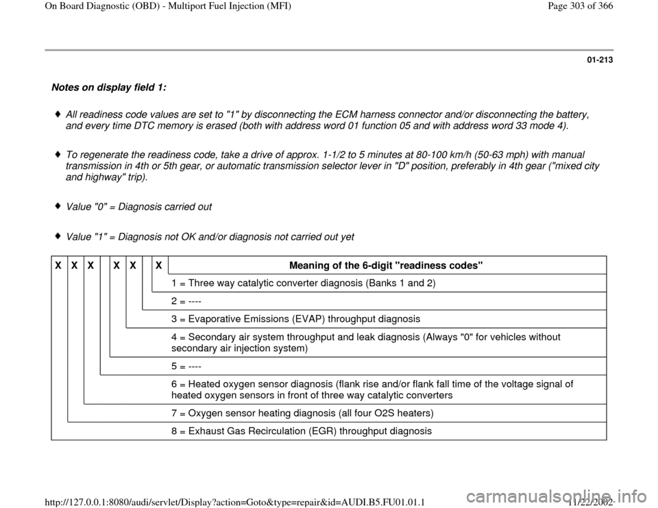
Notes on display field 1:
All readiness code values are set to "1" by disconnecting the ECM harness connector and/or disconnecting the battery,
and every time DTC memory is erased (both with address word 01 function 05 and with address word 33 mode 4).
To regenerate the readiness code, take a drive of approx. 1-1/2 to 5 minutes at 80-100 km/h (50-63 mph) with manual
transmission in 4th or 5th gear, or automatic transmission selector lever in "D" position, preferably in 4th gear ("mixed city
and highway" trip).
Value "0" = Diagnosis carried out
Value "1" = Diagnosis not OK and/or diagnosis not carried out yet
X
X
X
X
X
X
Meaning of the 6-digit "readiness codes"
1 = Three way catalytic converter diagnosis (Banks 1 and 2)
2 = ----
3 = Evaporative Emissions (EVAP) throughput diagnosis
4 = Secondary air system throughput and leak diagnosis (Always "0" for vehicles without
secondary air injection system)
5 = ----
6 = Heated oxygen sensor diagnosis (flank rise and/or flank fall time of the voltage signal of
heated oxygen sensors in front of three way catalytic converters
7 = Oxygen sensor heating diagnosis (all four O2S heaters)
8 = Exhaust Gas Recirculation (EGR) throughput diagnosis
Pa
ge 303 of 366 On Board Dia
gnostic
(OBD
) - Multi
port Fuel In
jection
(MFI
)
11/22/2002 htt
p://127.0.0.1:8080/audi/servlet/Dis
play?action=Goto&t
yp
e=re
pair&id=AUDI.B5.FU01.01.1
Page 304 of 366

01-214
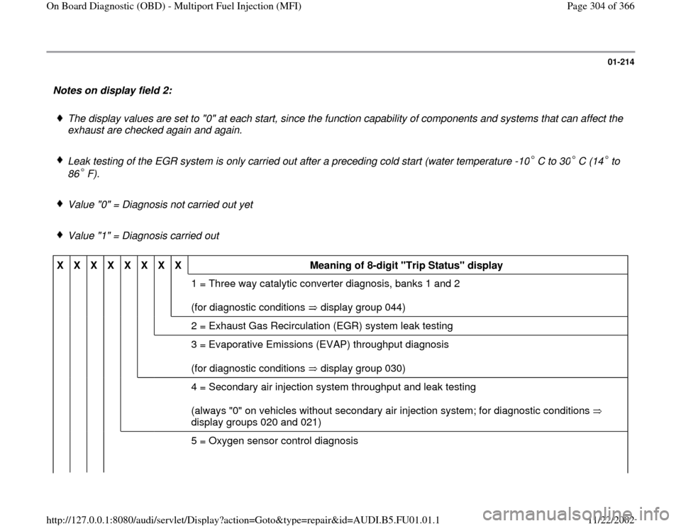
Notes on display field 2:
The display values are set to "0" at each start, since the function capability of components and systems that can affect the
exhaust are checked again and again.
Leak testing of the EGR system is only carried out after a preceding cold start (water temperature -10 C to 30 C (14 to
86 F). Value "0" = Diagnosis not carried out yet
Value "1" = Diagnosis carried out
X
X
X
X
X
X
X
X
Meaning of 8-digit "Trip Status" display
1 = Three way catalytic converter diagnosis, banks 1 and 2
(for diagnostic conditions display group 044)
2 = Exhaust Gas Recirculation (EGR) system leak testing
3 = Evaporative Emissions (EVAP) throughput diagnosis
(for diagnostic conditions display group 030)
4 = Secondary air injection system throughput and leak testing
(always "0" on vehicles without secondary air injection system; for diagnostic conditions
display groups 020 and 021)
5 = Oxygen sensor control diagnosis
Pa
ge 304 of 366 On Board Dia
gnostic
(OBD
) - Multi
port Fuel In
jection
(MFI
)
11/22/2002 htt
p://127.0.0.1:8080/audi/servlet/Dis
play?action=Goto&t
yp
e=re
pair&id=AUDI.B5.FU01.01.1
Page 305 of 366

(for diagnostic conditions display groups 007 and 008)
6 = Heated oxygen sensor diagnosis (flank rise and/or flank fall time of the voltage signal on
the heated oxygen sensor in front of three way catalytic converter; for diagnostic conditions
display group 042)
7 = Oxygen sensor heating diagnosis (all four O2S heaters)
8 = Exhaust Gas Recirculation (EGR) system throughput diagnosis
(for diagnostic conditions display group 017)
Pa
ge 305 of 366 On Board Dia
gnostic
(OBD
) - Multi
port Fuel In
jection
(MFI
)
11/22/2002 htt
p://127.0.0.1:8080/audi/servlet/Dis
play?action=Goto&t
yp
e=re
pair&id=AUDI.B5.FU01.01.1
Page 306 of 366

01-215
Notes on display fields 3 and 4:
Display field 3 evaluates all malfunctions except "Combustion misfiring and oxygen sensor control."
Display field 4 evaluates only the malfunctions "Combustion misfiring and oxygen sensor control"
If a malfunction is recognized, the corresponding counter will be set to "40." The counter is decremented, during a new
start, when the trip was started at coolant temperature of 49 C (120 F) and ended at a water temperature of 71 C
(160 F) and the malfunction is no longer recognized. However, decrementing is only allowed if the MIL has not lit up yet
or is no longer lit. When counter status "0" is reached, the recognized malfunction is erased. If the DTC memory is erased, the counter is also decremented.
Pa
ge 306 of 366 On Board Dia
gnostic
(OBD
) - Multi
port Fuel In
jection
(MFI
)
11/22/2002 htt
p://127.0.0.1:8080/audi/servlet/Dis
play?action=Goto&t
yp
e=re
pair&id=AUDI.B5.FU01.01.1