change wheel AUDI A4 1997 B5 / 1.G AHA ATQ Engines Cylinder Block Crankshaft And Flywheel Component Service Manual
[x] Cancel search | Manufacturer: AUDI, Model Year: 1997, Model line: A4, Model: AUDI A4 1997 B5 / 1.GPages: 33, PDF Size: 0.75 MB
Page 2 of 33

13-5
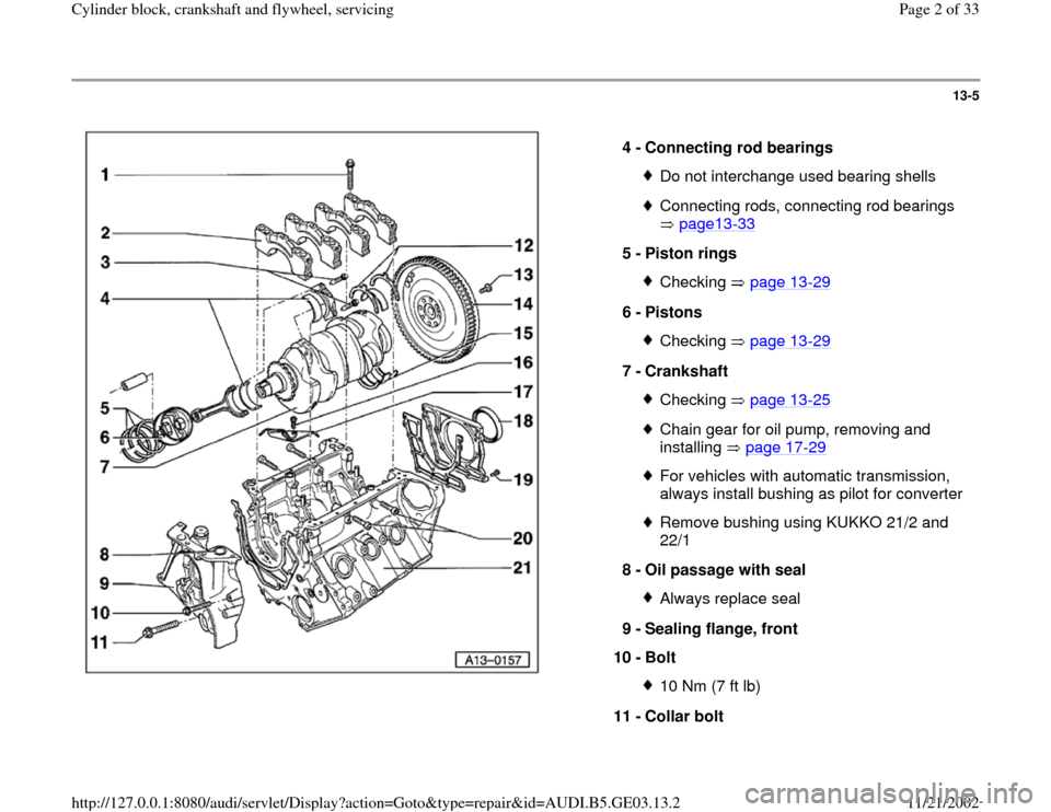
4 -
Connecting rod bearings
Do not interchange used bearing shellsConnecting rods, connecting rod bearings
page13
-33
5 -
Piston rings
Checking page 13
-29
6 -
Pistons
Checking page 13
-29
7 -
Crankshaft
Checking page 13
-25
Chain gear for oil pump, removing and
installing page 17
-29
For vehicles with automatic transmission,
always install bushing as pilot for converter Remove bushing using KUKKO 21/2 and
22/1
8 -
Oil passage with seal Always replace seal
9 -
Sealing flange, front
10 -
Bolt 10 Nm (7 ft lb)
11 -
Collar bolt
Pa
ge 2 of 33 C
ylinder block, crankshaft and fl
ywheel, servicin
g
11/21/2002 htt
p://127.0.0.1:8080/audi/servlet/Dis
play?action=Goto&t
yp
e=re
pair&id=AUDI.B5.GE03.13.2
Page 22 of 33

13-23
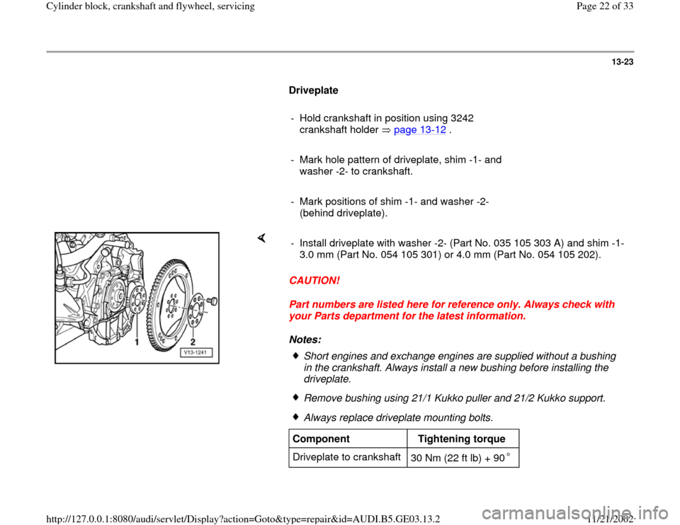
Driveplate
- Hold crankshaft in position using 3242
crankshaft holder page 13
-12
.
- Mark hole pattern of driveplate, shim -1- and
washer -2- to crankshaft.
- Mark positions of shim -1- and washer -2-
(behind driveplate).
CAUTION!
Part numbers are listed here for reference only. Always check with
your Parts department for the latest information.
Notes: - Install driveplate with washer -2- (Part No. 035 105 303 A) and shim -1-
3.0 mm (Part No. 054 105 301) or 4.0 mm (Part No. 054 105 202).
Short engines and exchange engines are supplied without a bushing
in the crankshaft. Always install a new bushing before installing the
driveplate. Remove bushing using 21/1 Kukko puller and 21/2 Kukko support.Always replace driveplate mounting bolts.
Component
Tightening torque
Driveplate to crankshaft
30 Nm (22 ft lb) + 90
Pa
ge 22 of 33 C
ylinder block, crankshaft and fl
ywheel, servicin
g
11/21/2002 htt
p://127.0.0.1:8080/audi/servlet/Dis
play?action=Goto&t
yp
e=re
pair&id=AUDI.B5.GE03.13.2
Page 24 of 33

13-25
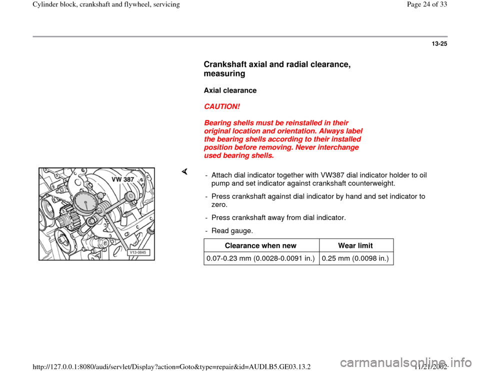
Crankshaft axial and radial clearance,
measuring
Axial clearance
CAUTION!
Bearing shells must be reinstalled in their
original location and orientation. Always label
the bearing shells according to their installed
position before removing. Never interchange
used bearing shells.
- Attach dial indicator together with VW387 dial indicator holder to oil
pump and set indicator against crankshaft counterweight.
- Press crankshaft against dial indicator by hand and set indicator to
zero.
- Press crankshaft away from dial indicator.
- Read gauge.
Clearance when new
Wear limit
0.07-0.23 mm (0.0028-0.0091 in.) 0.25 mm (0.0098 in.)
Pa
ge 24 of 33 C
ylinder block, crankshaft and fl
ywheel, servicin
g
11/21/2002 htt
p://127.0.0.1:8080/audi/servlet/Dis
play?action=Goto&t
yp
e=re
pair&id=AUDI.B5.GE03.13.2
Page 32 of 33

13-33
Connecting rod and connecting rod
bearings, checking clearance
Notes:
Replace the connecting rods only as a set.
Do not interchange connecting rod bearings.
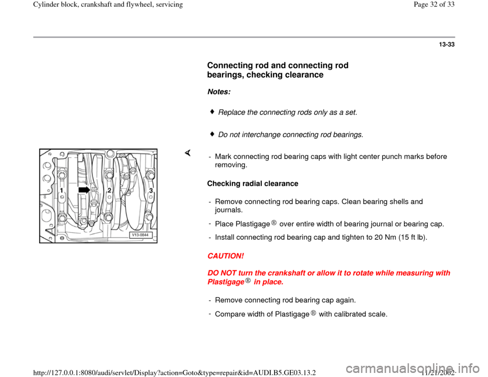
Checking radial clearance
CAUTION!
DO NOT turn the crankshaft or allow it to rotate while measuring with
Plastigage in place. - Mark connecting rod bearing caps with light center punch marks before
removing.
- Remove connecting rod bearing caps. Clean bearing shells and
journals.
-
Place Plastigage over entire width of bearing journal or bearing cap.- Install connecting rod bearing cap and tighten to 20 Nm (15 ft lb).- Remove connecting rod bearing cap again.
-
Compare width of Plastigage with calibrated scale.
Pa
ge 32 of 33 C
ylinder block, crankshaft and fl
ywheel, servicin
g
11/21/2002 htt
p://127.0.0.1:8080/audi/servlet/Dis
play?action=Goto&t
yp
e=re
pair&id=AUDI.B5.GE03.13.2