diagram AUDI A4 1997 B5 / 1.G APB Engine Cooling System Components
[x] Cancel search | Manufacturer: AUDI, Model Year: 1997, Model line: A4, Model: AUDI A4 1997 B5 / 1.GPages: 34, PDF Size: 0.64 MB
Page 3 of 34
19-2
Cooling system components (on body),
removing and installing
Notes:
Parts of cooling system on engine Page 19
-
8 .
Diagram of coolant hose connections Page 19
-17
.
Draining and filling with coolant Page 19
-
19
.
Coolant mixture ratios Page 19
-19
, draining
and filling cooling system.
Pa
ge 3 of 34 Coolin
g system com
ponents, removin
g and installin
g
11/21/2002 htt
p://127.0.0.1:8080/audi/servlet/Dis
play?action=Goto&t
yp
e=re
pair&id=AUDI.B5.GE05.19.1
Page 4 of 34

19-3
1 -
Radiator
Removing and installing Page 19
-26
After replacing, replace coolant in complete
system
2 -
Securing clip
3 -
Securing rubber
4 -
O-ring Replace if damaged
5 -
Bottom coolant hose Secured to radiator with retaining clipCheck for secure seatingDiagram of coolant hose connections
Page 19
-17
6 -
Rubber washer
Pa
ge 4 of 34 Coolin
g system com
ponents, removin
g and installin
g
11/21/2002 htt
p://127.0.0.1:8080/audi/servlet/Dis
play?action=Goto&t
yp
e=re
pair&id=AUDI.B5.GE05.19.1
Page 6 of 34
19-5
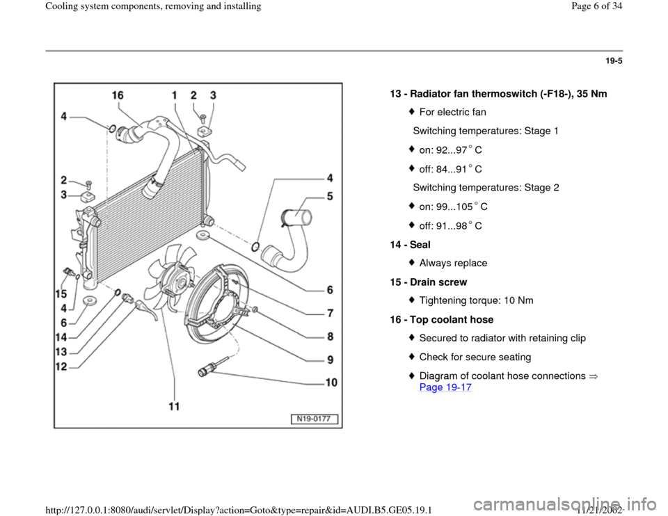
13 -
Radiator fan thermoswitch (-F18-), 35 Nm
For electric fan
Switching temperatures: Stage 1on: 92...97 Coff: 84...91 C
Switching temperatures: Stage 2
on: 99...105 Coff: 91...98 C
14 -
Seal
Always replace
15 -
Drain screw Tightening torque: 10 Nm
16 -
Top coolant hose Secured to radiator with retaining clipCheck for secure seatingDiagram of coolant hose connections
Page 19
-17
Pa
ge 6 of 34 Coolin
g system com
ponents, removin
g and installin
g
11/21/2002 htt
p://127.0.0.1:8080/audi/servlet/Dis
play?action=Goto&t
yp
e=re
pair&id=AUDI.B5.GE05.19.1
Page 10 of 34
19-9
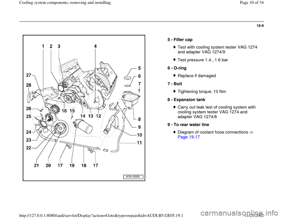
5 -
Filler cap
Test with cooling system tester VAG 1274
and adapter VAG 1274/9 Test pressure 1.4...1.6 bar
6 -
O-ring Replace if damaged
7 -
Bolt Tightening torque: 10 Nm
8 -
Expansion tank Carry out leak test of cooling system with
cooling system tester VAG 1274 and
adapter VAG 1274/8
9 -
To rear water line Diagram of coolant hose connections
Page 19
-17
Pa
ge 10 of 34 Coolin
g system com
ponents, removin
g and installin
g
11/21/2002 htt
p://127.0.0.1:8080/audi/servlet/Dis
play?action=Goto&t
yp
e=re
pair&id=AUDI.B5.GE05.19.1
Page 11 of 34
19-10
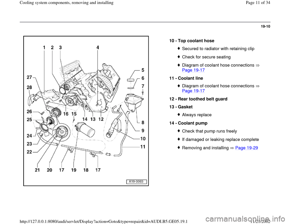
10 -
Top coolant hose
Secured to radiator with retaining clipCheck for secure seatingDiagram of coolant hose connections
Page 19
-17
11 -
Coolant line
Diagram of coolant hose connections
Page 19
-17
12 -
Rear toothed belt guard
13 -
Gasket
Always replace
14 -
Coolant pump Check that pump runs freelyIf damaged or leaking replace completeRemoving and installing Page 19
-29
Pa
ge 11 of 34 Coolin
g system com
ponents, removin
g and installin
g
11/21/2002 htt
p://127.0.0.1:8080/audi/servlet/Dis
play?action=Goto&t
yp
e=re
pair&id=AUDI.B5.GE05.19.1
Page 12 of 34
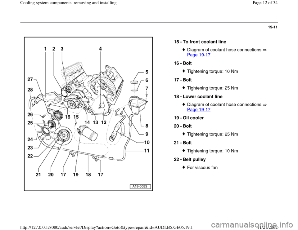
19-11
15 -
To front coolant line
Diagram of coolant hose connections
Page 19
-17
16 -
Bolt
Tightening torque: 10 Nm
17 -
Bolt Tightening torque: 25 Nm
18 -
Lower coolant line Diagram of coolant hose connections
Page 19
-17
19 -
Oil cooler
20 -
Bolt
Tightening torque: 25 Nm
21 -
Bolt Tightening torque: 10 Nm
22 -
Belt pulley For viscous fan
Pa
ge 12 of 34 Coolin
g system com
ponents, removin
g and installin
g
11/21/2002 htt
p://127.0.0.1:8080/audi/servlet/Dis
play?action=Goto&t
yp
e=re
pair&id=AUDI.B5.GE05.19.1
Page 13 of 34
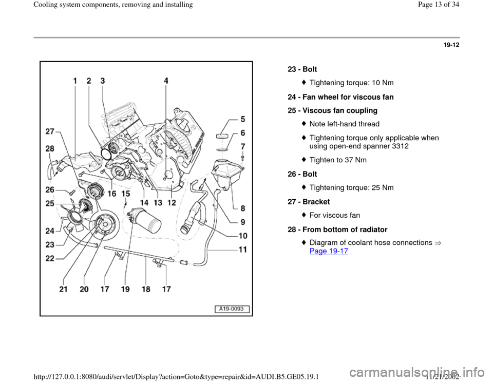
19-12
23 -
Bolt
Tightening torque: 10 Nm
24 -
Fan wheel for viscous fan
25 -
Viscous fan coupling Note left-hand threadTightening torque only applicable when
using open-end spanner 3312 Tighten to 37 Nm
26 -
Bolt Tightening torque: 25 Nm
27 -
Bracket For viscous fan
28 -
From bottom of radiator Diagram of coolant hose connections
Page 19
-17
Pa
ge 13 of 34 Coolin
g system com
ponents, removin
g and installin
g
11/21/2002 htt
p://127.0.0.1:8080/audi/servlet/Dis
play?action=Goto&t
yp
e=re
pair&id=AUDI.B5.GE05.19.1
Page 14 of 34
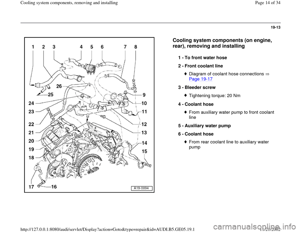
19-13
Cooling system components (on engine,
rear), removing and installing
1 -
To front water hose
2 -
Front coolant line
Diagram of coolant hose connections
Page 19
-17
3 -
Bleeder screw
Tightening torque: 20 Nm
4 -
Coolant hose From auxiliary water pump to front coolant
line
5 -
Auxiliary water pump
6 -
Coolant hose From rear coolant line to auxiliary water
pump
Pa
ge 14 of 34 Coolin
g system com
ponents, removin
g and installin
g
11/21/2002 htt
p://127.0.0.1:8080/audi/servlet/Dis
play?action=Goto&t
yp
e=re
pair&id=AUDI.B5.GE05.19.1
Page 15 of 34
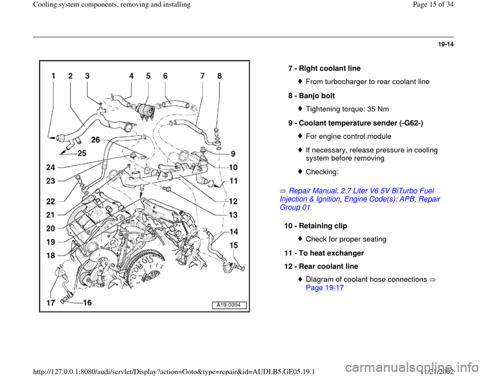
19-14
Repair Manual, 2.7 Liter V6 5V BiTurbo Fuel
Injection & Ignition, Engine Code(s): APB, Repair Group 01
7 -
Right coolant line From turbocharger to rear coolant line
8 -
Banjo bolt Tightening torque: 35 Nm
9 -
Coolant temperature sender (-G62-) For engine control moduleIf necessary, release pressure in cooling
system before removing Checking:
10 -
Retaining clip
Check for proper seating
11 -
To heat exchanger
12 -
Rear coolant line Diagram of coolant hose connections
Page 19
-17
Pa
ge 15 of 34 Coolin
g system com
ponents, removin
g and installin
g
11/21/2002 htt
p://127.0.0.1:8080/audi/servlet/Dis
play?action=Goto&t
yp
e=re
pair&id=AUDI.B5.GE05.19.1
Page 17 of 34
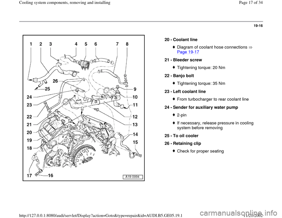
19-16
20 -
Coolant line
Diagram of coolant hose connections
Page 19
-17
21 -
Bleeder screw
Tightening torque: 20 Nm
22 -
Banjo bolt Tightening torque: 35 Nm
23 -
Left coolant line From turbocharger to rear coolant line
24 -
Sender for auxiliary water pump 2-pinIf necessary, release pressure in cooling
system before removing
25 -
To oil cooler
26 -
Retaining clip Check for proper seating
Pa
ge 17 of 34 Coolin
g system com
ponents, removin
g and installin
g
11/21/2002 htt
p://127.0.0.1:8080/audi/servlet/Dis
play?action=Goto&t
yp
e=re
pair&id=AUDI.B5.GE05.19.1