engine coolant AUDI A4 1997 B5 / 1.G APB Engine Cooling System Components
[x] Cancel search | Manufacturer: AUDI, Model Year: 1997, Model line: A4, Model: AUDI A4 1997 B5 / 1.GPages: 34, PDF Size: 0.64 MB
Page 1 of 34
19-1
Cooling system components,
removing and installing
WARNING!
Hot steam can escape from the expansion
tank when the filler cap is opened. Cover the
filler cap with a cloth and unscrew it carefully.
Notes:
When the engine is hot the cooling system is
under pressure. Carefully open filler cap on
expansion tank to release pressure before
starting repair work.
Hoses are secured with spring-type clips. When
repairing only use spring-type clips.
VAG 1921 pliers are recommended when
installing spring-type clips.
The O-rings fitted at the quick-release
connections must be replaceed if damaged or
leaking.
When installing coolant hoses, ensure that they
are free of stress and do not come into contact
with other components (observe markings on
coolant connection and hose).
Pa
ge 1 of 34 Coolin
g system com
ponents, removin
g and installin
g
11/21/2002 htt
p://127.0.0.1:8080/audi/servlet/Dis
play?action=Goto&t
yp
e=re
pair&id=AUDI.B5.GE05.19.1
Page 3 of 34
19-2
Cooling system components (on body),
removing and installing
Notes:
Parts of cooling system on engine Page 19
-
8 .
Diagram of coolant hose connections Page 19
-17
.
Draining and filling with coolant Page 19
-
19
.
Coolant mixture ratios Page 19
-19
, draining
and filling cooling system.
Pa
ge 3 of 34 Coolin
g system com
ponents, removin
g and installin
g
11/21/2002 htt
p://127.0.0.1:8080/audi/servlet/Dis
play?action=Goto&t
yp
e=re
pair&id=AUDI.B5.GE05.19.1
Page 14 of 34
19-13
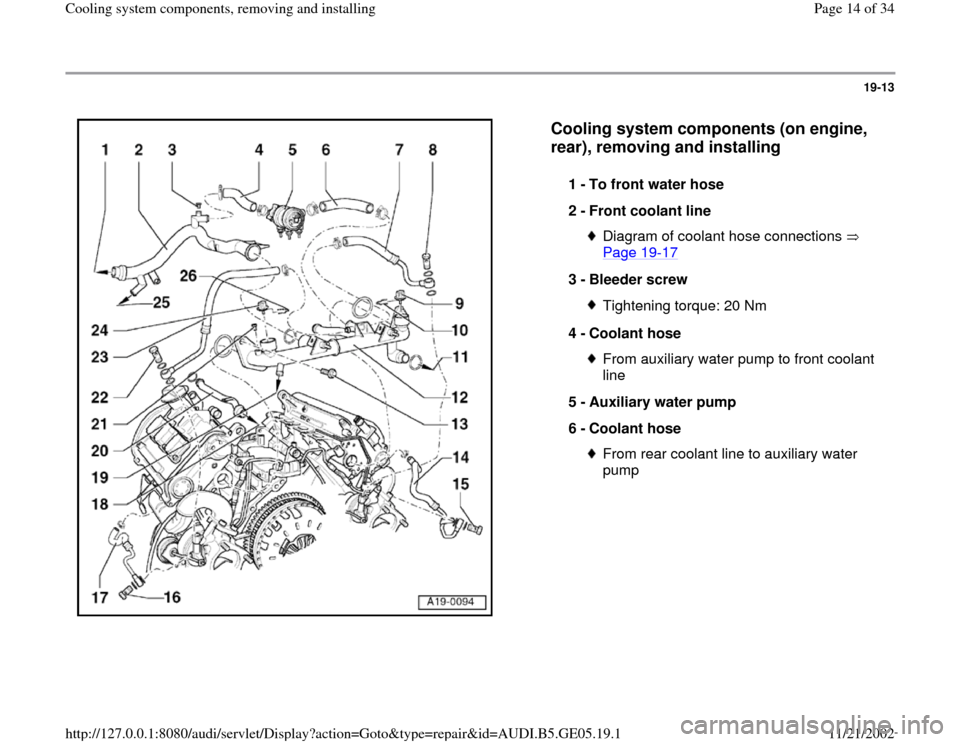
Cooling system components (on engine,
rear), removing and installing
1 -
To front water hose
2 -
Front coolant line
Diagram of coolant hose connections
Page 19
-17
3 -
Bleeder screw
Tightening torque: 20 Nm
4 -
Coolant hose From auxiliary water pump to front coolant
line
5 -
Auxiliary water pump
6 -
Coolant hose From rear coolant line to auxiliary water
pump
Pa
ge 14 of 34 Coolin
g system com
ponents, removin
g and installin
g
11/21/2002 htt
p://127.0.0.1:8080/audi/servlet/Dis
play?action=Goto&t
yp
e=re
pair&id=AUDI.B5.GE05.19.1
Page 15 of 34
19-14
Repair Manual, 2.7 Liter V6 5V BiTurbo Fuel
Injection & Ignition, Engine Code(s): APB, Repair Group 01
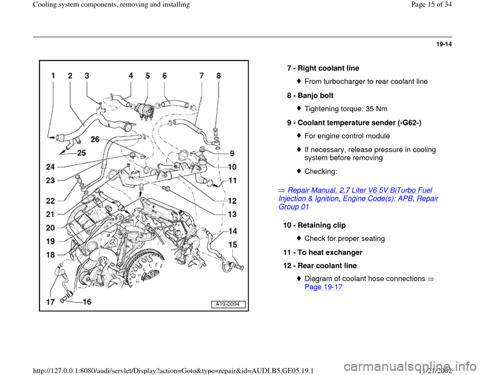
7 -
Right coolant line From turbocharger to rear coolant line
8 -
Banjo bolt Tightening torque: 35 Nm
9 -
Coolant temperature sender (-G62-) For engine control moduleIf necessary, release pressure in cooling
system before removing Checking:
10 -
Retaining clip
Check for proper seating
11 -
To heat exchanger
12 -
Rear coolant line Diagram of coolant hose connections
Page 19
-17
Pa
ge 15 of 34 Coolin
g system com
ponents, removin
g and installin
g
11/21/2002 htt
p://127.0.0.1:8080/audi/servlet/Dis
play?action=Goto&t
yp
e=re
pair&id=AUDI.B5.GE05.19.1
Page 16 of 34
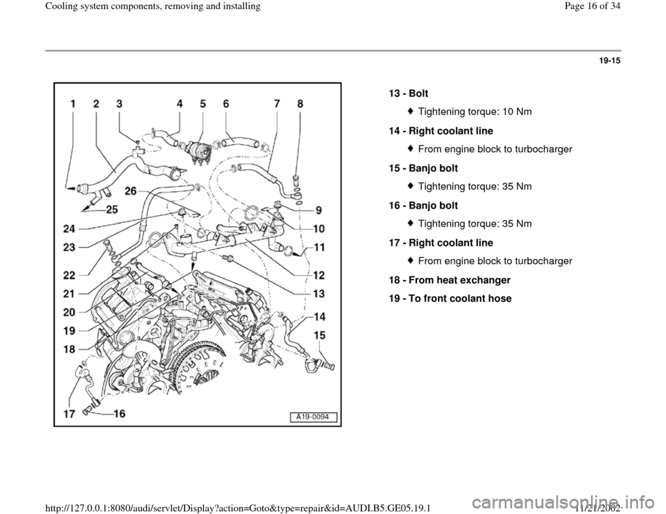
19-15
13 -
Bolt
Tightening torque: 10 Nm
14 -
Right coolant line From engine block to turbocharger
15 -
Banjo bolt Tightening torque: 35 Nm
16 -
Banjo bolt Tightening torque: 35 Nm
17 -
Right coolant line From engine block to turbocharger
18 -
From heat exchanger
19 -
To front coolant hose
Pa
ge 16 of 34 Coolin
g system com
ponents, removin
g and installin
g
11/21/2002 htt
p://127.0.0.1:8080/audi/servlet/Dis
play?action=Goto&t
yp
e=re
pair&id=AUDI.B5.GE05.19.1
Page 18 of 34
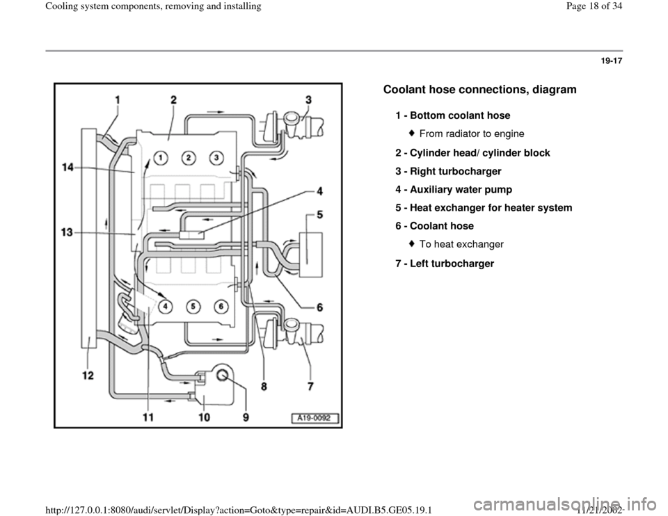
19-17
Coolant hose connections, diagram
1 -
Bottom coolant hose
From radiator to engine
2 -
Cylinder head/ cylinder block
3 -
Right turbocharger
4 -
Auxiliary water pump
5 -
Heat exchanger for heater system
6 -
Coolant hose To heat exchanger
7 -
Left turbocharger
Pa
ge 18 of 34 Coolin
g system com
ponents, removin
g and installin
g
11/21/2002 htt
p://127.0.0.1:8080/audi/servlet/Dis
play?action=Goto&t
yp
e=re
pair&id=AUDI.B5.GE05.19.1
Page 20 of 34
19-19
Cooling system, draining and filling
Draining
WARNING!
Hot steam can escape from the expansion
tank when the filler cap is opened. Cover the
filler cap with a cloth and remove it carefully.
- Remove filler cap on coolant expansion tank.
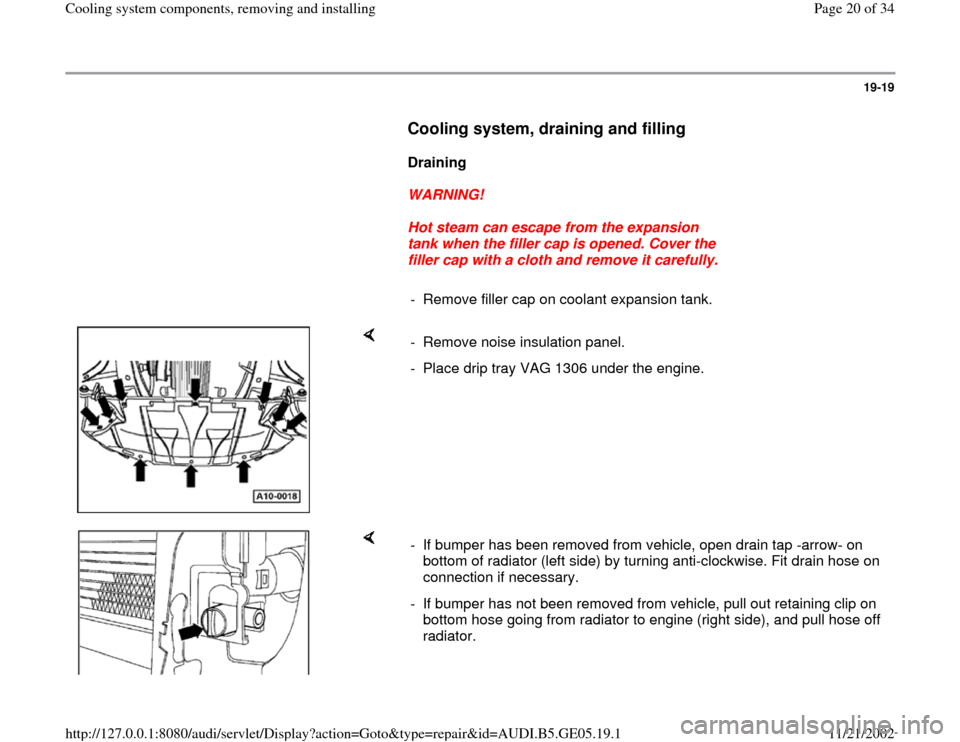
- Remove noise insulation panel.
- Place drip tray VAG 1306 under the engine.
- If bumper has been removed from vehicle, open drain tap -arrow- on
bottom of radiator (left side) by turning anti-clockwise. Fit drain hose on
connection if necessary.
- If bumper has not been removed from vehicle, pull out retaining clip on
bottom hose going from radiator to engine (right side), and pull hose off
radiator.
Pa
ge 20 of 34 Coolin
g system com
ponents, removin
g and installin
g
11/21/2002 htt
p://127.0.0.1:8080/audi/servlet/Dis
play?action=Goto&t
yp
e=re
pair&id=AUDI.B5.GE05.19.1
Page 21 of 34
19-20
Note:
Observe disposal regulations for coolant.
Filling
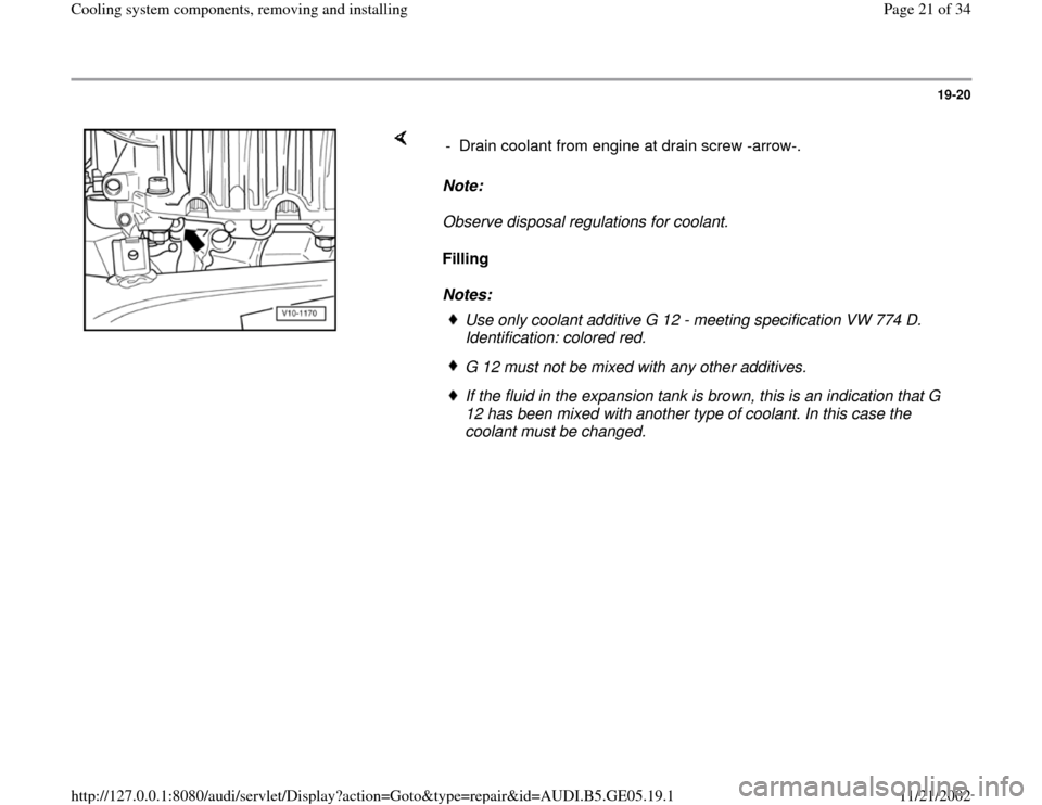
Notes: - Drain coolant from engine at drain screw -arrow-.
Use only coolant additive G 12 - meeting specification VW 774 D.
Identification: colored red. G 12 must not be mixed with any other additives. If the fluid in the expansion tank is brown, this is an indication that G
12 has been mixed with another type of coolant. In this case the
coolant must be changed.
Pa
ge 21 of 34 Coolin
g system com
ponents, removin
g and installin
g
11/21/2002 htt
p://127.0.0.1:8080/audi/servlet/Dis
play?action=Goto&t
yp
e=re
pair&id=AUDI.B5.GE05.19.1
Page 22 of 34
19-21
G 12 and coolant additives complying with
specification "VW 774 D" prevent frost and
corrosion damage, scaling and also raise the
boiling point of the coolant. For this reason the
system must be filled all year round with the
correct additive for frost and corrosion
protection.
Particularly in countries with tropical climates,
the higher boiling point of the coolant improves
engine reliability when working under heavy
load.
The system must be protected against frost to
about -25 C (in arctic climates to about -35
C).
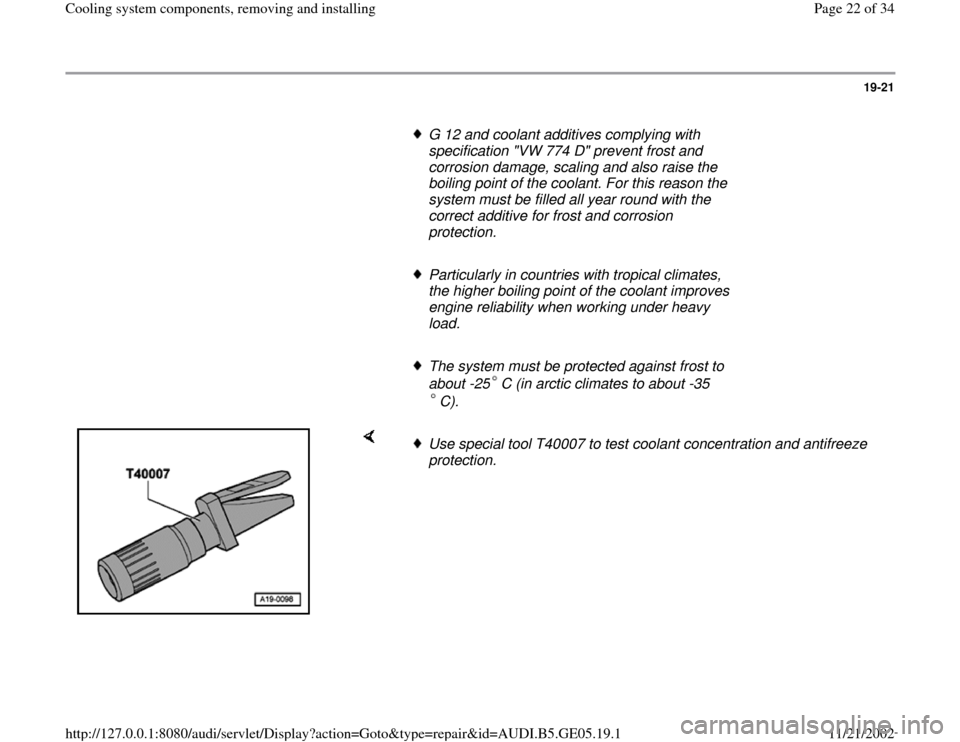
Use special tool T40007 to test coolant concentration and antifreeze
protection.
Pa
ge 22 of 34 Coolin
g system com
ponents, removin
g and installin
g
11/21/2002 htt
p://127.0.0.1:8080/audi/servlet/Dis
play?action=Goto&t
yp
e=re
pair&id=AUDI.B5.GE05.19.1
Page 25 of 34
19-23
- Replace O-ring on coolant drain screw and
screw drain screw back into engine.
Tightening torque: 20 Nm
- Install bottom coolant hose and secure.
- Close coolant drain tap on radiator.
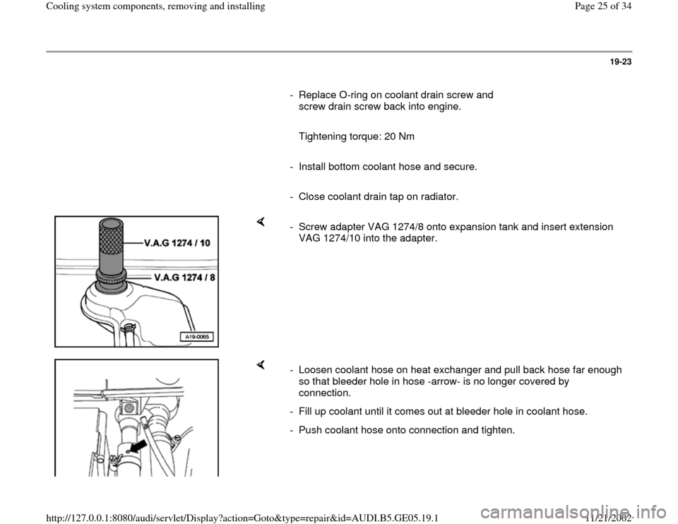
- Screw adapter VAG 1274/8 onto expansion tank and insert extension
VAG 1274/10 into the adapter.
- Loosen coolant hose on heat exchanger and pull back hose far enough
so that bleeder hole in hose -arrow- is no longer covered by
connection.
- Fill up coolant until it comes out at bleeder hole in coolant hose.
- Push coolant hose onto connection and tighten.
Pa
ge 25 of 34 Coolin
g system com
ponents, removin
g and installin
g
11/21/2002 htt
p://127.0.0.1:8080/audi/servlet/Dis
play?action=Goto&t
yp
e=re
pair&id=AUDI.B5.GE05.19.1