sensor AUDI A4 1997 B5 / 1.G APB Engine Electronic Engine Power Control Checking Workshop Manual
[x] Cancel search | Manufacturer: AUDI, Model Year: 1997, Model line: A4, Model: AUDI A4 1997 B5 / 1.GPages: 39, PDF Size: 0.16 MB
Page 1 of 39
24-139
Electronic Engine Power
Control (EPC), checking
Function of Engine Power Control (EPC)
With the electronic throttle, the throttle valve is
not operated by a cable connected to the
accelerator pedal. There is no mechanical link
between the accelerator pedal and the throttle
valve.
The throttle valve is actuated by a servomotor
(throttle valve positioner) in the throttle valve
control module over the full range of engine
speeds and load conditions.
The throttle valve positioner actuates the throttle
valve according to the commands it receives
from the Engine Control Module (ECM).
The position of the accelerator pedal is
communicated to the Engine Control Module
(ECM) by two accelerator position sensors
(variable resistors, both installed in a single
housing) which are connected to the accelerator
pedal.
The accelerator pedal position (as determined by
the driver) is one of the main input values for the
Engine Control Module (ECM).
Pa
ge 1 of 39 Electronic En
gine Power Control
(EPC
), checkin
g
11/22/2002 htt
p://127.0.0.1:8080/audi/servlet/Dis
play?action=Goto&t
yp
e=re
pair&id=AUDI.B5.FU04.24.4
Page 2 of 39
24-140
With the engine is not running and the ignition
switched on, the ECM operates the throttle valve
positioner in exact accordance with the signals
from the accelerator position sensors. For
example, when the accelerator pedal is pressed
down half way, the throttle valve positioner opens
the throttle valve by an equivalent amount, i.e.
about half way.
When the engine is running (i.e. under load) the
ECM can open and close the throttle valve freely,
independently of the signals being sent by the
accelerator position sensors.
For example, the throttle valve might already be
fully open even though the accelerator pedal is
only pressed down half way. This has the
advantage of preventing throttling losses at the
throttle valve.
Pa
ge 2 of 39 Electronic En
gine Power Control
(EPC
), checkin
g
11/22/2002 htt
p://127.0.0.1:8080/audi/servlet/Dis
play?action=Goto&t
yp
e=re
pair&id=AUDI.B5.FU04.24.4
Page 3 of 39
24-141
Under certain engine load conditions there is
also a significant reduction in harmful emissions
and noticeably improved fuel consumption.
The Engine Control Module (ECM) can provide
the optimum combination of throttle valve
opening and charge pressure in order to create
the required torque.
The electronic throttle is not simply a
combination of two or three components, but
rather a complete system comprising all the
elements that together determine the position of
the throttle valve and also control and monitor it.
For example, the Accelerator Pedal Position
Sensor, Throttle Valve Control Module, EPC
warning lamp, Engine Control Module (ECM)
etc.
Pa
ge 3 of 39 Electronic En
gine Power Control
(EPC
), checkin
g
11/22/2002 htt
p://127.0.0.1:8080/audi/servlet/Dis
play?action=Goto&t
yp
e=re
pair&id=AUDI.B5.FU04.24.4
Page 9 of 39
24-145
Throttle Valve Control Module -J338,
checking
The throttle valve control module housing
contains the following components:
CAUTION!
The housing should NOT be opened.
Throttle drive -G186 (power accelerator
actuation) (This is an electric motor activated by
the engine control module. The motor opens
the throttle valve by applying force to overcome
the spring pressure.)
Angle sensor -1- for throttle drive (power
accelerator actuation) -G187
Angle sensor -2- for throttle drive (power
accelerator actuation) -G188
Notes:
The angle sensors are in the form of
potentiometers (variable resistors). Each sends
its own separate signal to inform the engine
control module of the position of the throttle
valve (i.e. one of the signals is redundant).
Pa
ge 9 of 39 Electronic En
gine Power Control
(EPC
), checkin
g
11/22/2002 htt
p://127.0.0.1:8080/audi/servlet/Dis
play?action=Goto&t
yp
e=re
pair&id=AUDI.B5.FU04.24.4
Page 11 of 39
24-146
Throttle valve control module,
adaptation
The adaptation process enables the Engine
Control Module (ECM) to learn the different
positions of the throttle valve with the ignition
switched on and the engine not running. These
positions are stored in the control module. The
feedback signal indicating the position of the
throttle valve comes from the two angle sensors
for throttle valve drive.
If the Throttle Valve Control Module -J338 or the
ECM is removed and installed or replaced, or if
the voltage (power) supply to the ECM is
interrupted, an adaptation must be carried out.
Pa
ge 11 of 39 Electronic En
gine Power Control
(EPC
), checkin
g
11/22/2002 htt
p://127.0.0.1:8080/audi/servlet/Dis
play?action=Goto&t
yp
e=re
pair&id=AUDI.B5.FU04.24.4
Page 12 of 39
24-147
The learning process (adaptation process) is
carried out:
By selecting "Basic Setting" (function 04),
Display Group 060 with the ignition switched
on.
Automatically if the ignition is switched on for at
least 6 seconds without operating the starter or
depressing the accelerator, and if the Engine
Control Module (ECM) registers a "learning
requirement." (In this case, however, there is no
way of knowing whether the adaptation process
was successful or not.) The engine control
module will register a learning requirement if
the previously stored voltage readings from the
angle sensors do not correspond (within a
certain tolerance range) to the new voltage
readings.
Note:
The engine will not start during automatic
adaptation.
Pa
ge 12 of 39 Electronic En
gine Power Control
(EPC
), checkin
g
11/22/2002 htt
p://127.0.0.1:8080/audi/servlet/Dis
play?action=Goto&t
yp
e=re
pair&id=AUDI.B5.FU04.24.4
Page 15 of 39
24-150
When the -Q- button is pressed the throttle valve
positioner will be switched mechanically.
In this condition the throttle valve is pulled into an
"emergency running" or default position by a
mechanical spring in the throttle valve control
module. The values supplied by the two angle
sensors for this emergency running position are
stored in the Engine Control Module (ECM).
The throttle valve is then opened by a
predetermined amount. As soon as it reaches
this position the current supply to the throttle
valve positioner is again disconnected. The
spring should then close the throttle valve
mechanically to the previously learned default
position within a specified period of time (spring
test).
The throttle valve positioner then closes the
throttle valve and the values supplied by the
angle sensors in the throttle valve control module
are stored in the Engine Control Module (ECM).
If the ECM disconnects the current supply to the
throttle valve positioner while the vehicle is being
driven, the result will be an increase in idling
speed with fluctuating engine RPM (hunting) and
very slow throttle response.
Pa
ge 15 of 39 Electronic En
gine Power Control
(EPC
), checkin
g
11/22/2002 htt
p://127.0.0.1:8080/audi/servlet/Dis
play?action=Goto&t
yp
e=re
pair&id=AUDI.B5.FU04.24.4
Page 16 of 39
24-151
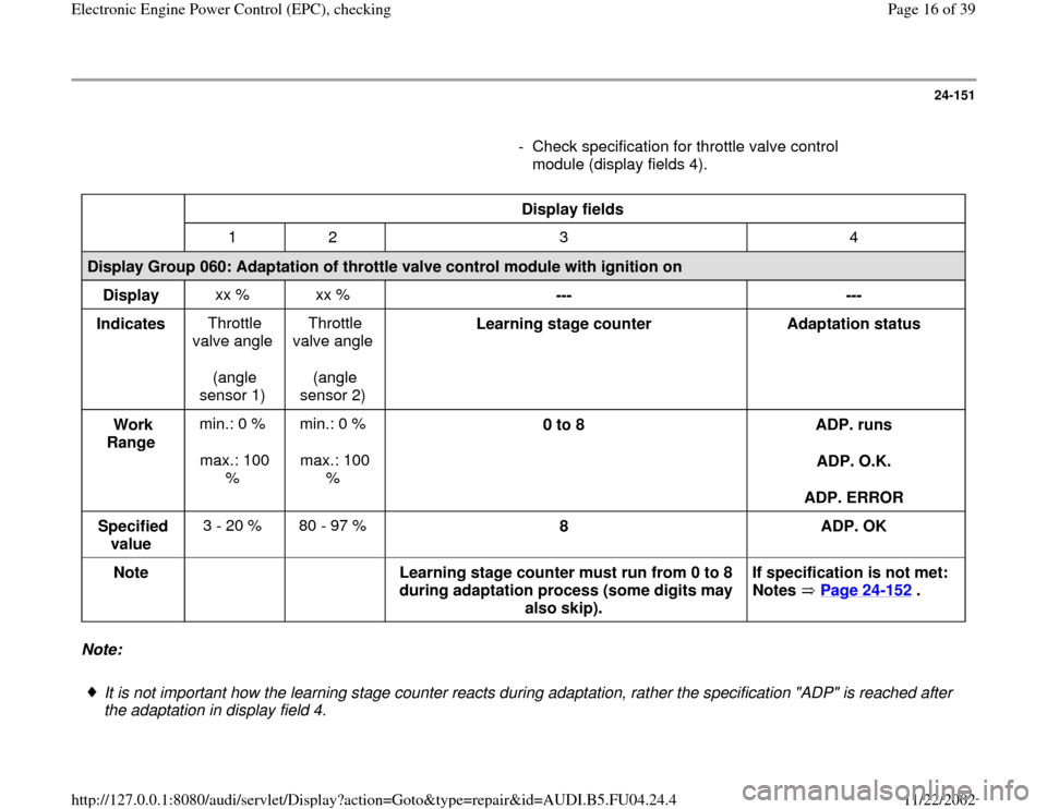
- Check specification for throttle valve control
module (display fields 4).
Display fields
1 2 3 4
Display Group 060: Adaptation of throttle valve control module with ignition on
Display xx % xx %
---
---
Indicates Throttle
valve angle
(angle
sensor 1) Throttle
valve angle
(angle
sensor 2) Learning stage counter
Adaptation status
Work
Range min.: 0 %
max.: 100
% min.: 0 %
max.: 100
% 0 to 8
ADP. runs
ADP. O.K.
ADP. ERROR
Specified
value 3 - 20 % 80 - 97 %
8
ADP. OK
Note
Learning stage counter must run from 0 to 8
during adaptation process (some digits may
also skip). If specification is not met:
Notes Page 24
-152
.
Note:
It is not important how the learning stage counter reacts during adaptation, rather the specification "ADP" is reached after
the adaptation in display field 4.
Pa
ge 16 of 39 Electronic En
gine Power Control
(EPC
), checkin
g
11/22/2002 htt
p://127.0.0.1:8080/audi/servlet/Dis
play?action=Goto&t
yp
e=re
pair&id=AUDI.B5.FU04.24.4
Page 20 of 39
24-153
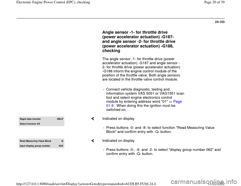
Angle sensor -1- for throttle drive
(power accelerator actuation) -G187-
and angle sensor -2- for throttle drive
(power accelerator actuation) -G188,
checking
The angle sensor -1- for throttle drive (power
accelerator actuation) -G187 and angle sensor -
2- for throttle drive (power accelerator actuation)
-G188 inform the engine control module of the
position of the throttle valve. Both angle sensors
are located in the throttle valve control module.
- Connect vehicle diagnostic, testing and
information system VAS 5051 or VAG1551 scan
tool and select engine electronics control
module by entering address word "01" Page
01
-9 . When doing this the ignition must be
switched on.
Rapid data transfer
HELP
Select function XX
Indicated on display
- Press buttons -0- and -8- to select function "Read Measuring Value
Block" and confirm entry with -Q- button.
Read Measurin
g Value Block
Q
Input displa
y group number
XXX
Indicated on display
- Press buttons -0-, -6- and -2- to select "display group number 062" and
confirm entry with -Q- button.
Pa
ge 20 of 39 Electronic En
gine Power Control
(EPC
), checkin
g
11/22/2002 htt
p://127.0.0.1:8080/audi/servlet/Dis
play?action=Goto&t
yp
e=re
pair&id=AUDI.B5.FU04.24.4
Page 21 of 39
24-154
Note:
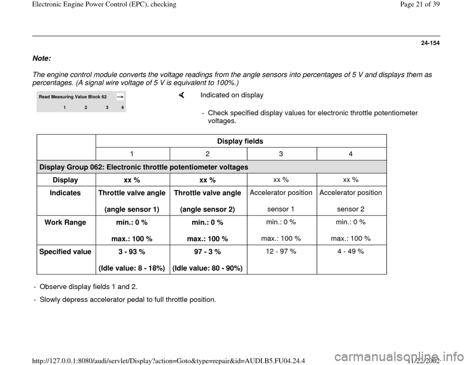
The engine control module converts the voltage readings from the angle sensors into percentages of 5 V and displays them as percentages. (A signal wire voltage of 5 V is equivalent to 100%.) Read Measuring Value Block 62
1
2
3
4
Indicated on display
- Check specified display values for electronic throttle potentiometer
voltages.
Display fields
1 2 3 4
Display Group 062: Electronic throttle potentiometer voltages
Display
xx %
xx % xx % xx %
Indicates
Throttle valve angle
(angle sensor 1) Throttle valve angle
(angle sensor 2) Accelerator position
sensor 1 Accelerator position
sensor 2
Work Range
min.: 0 %
max.: 100 % min.: 0 %
max.: 100 % min.: 0 %
max.: 100 % min.: 0 %
max.: 100 %
Specified value
3 - 93 %
(Idle value: 8 - 18%) 97 - 3 %
(Idle value: 80 - 90%) 12 - 97 % 4 - 49 % - Observe display fields 1 and 2.
- Slowly depress accelerator pedal to full throttle position.
Pa
ge 21 of 39 Electronic En
gine Power Control
(EPC
), checkin
g
11/22/2002 htt
p://127.0.0.1:8080/audi/servlet/Dis
play?action=Goto&t
yp
e=re
pair&id=AUDI.B5.FU04.24.4