check engine AUDI A4 1997 B5 / 1.G APB Engine Valve Gear Service Workshop Manual
[x] Cancel search | Manufacturer: AUDI, Model Year: 1997, Model line: A4, Model: AUDI A4 1997 B5 / 1.GPages: 99, PDF Size: 1.78 MB
Page 33 of 99
15-33
Note:
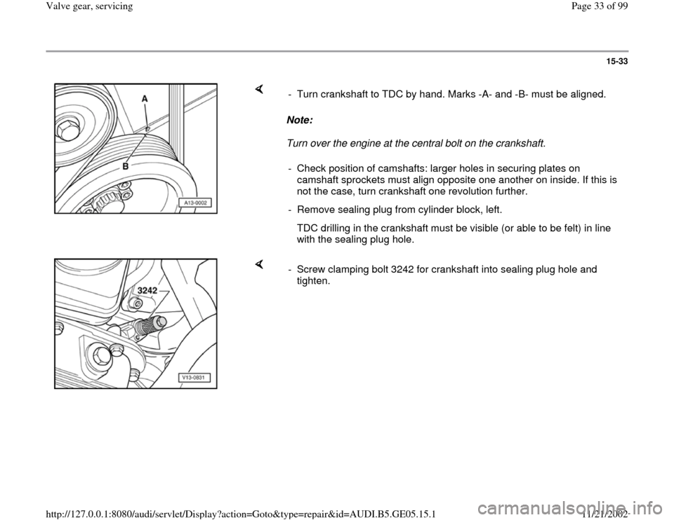
Turn over the engine at the central bolt on the crankshaft. - Turn crankshaft to TDC by hand. Marks -A- and -B- must be aligned.
- Check position of camshafts: larger holes in securing plates on
camshaft sprockets must align opposite one another on inside. If this is
not the case, turn crankshaft one revolution further.
- Remove sealing plug from cylinder block, left.
TDC drilling in the crankshaft must be visible (or able to be felt) in line
with the sealing plug hole.
- Screw clamping bolt 3242 for crankshaft into sealing plug hole and
tighten.
Pa
ge 33 of 99 Valve
gear, servicin
g
11/21/2002 htt
p://127.0.0.1:8080/audi/servlet/Dis
play?action=Goto&t
yp
e=re
pair&id=AUDI.B5.GE05.15.1
Page 47 of 99
15-47
Note:
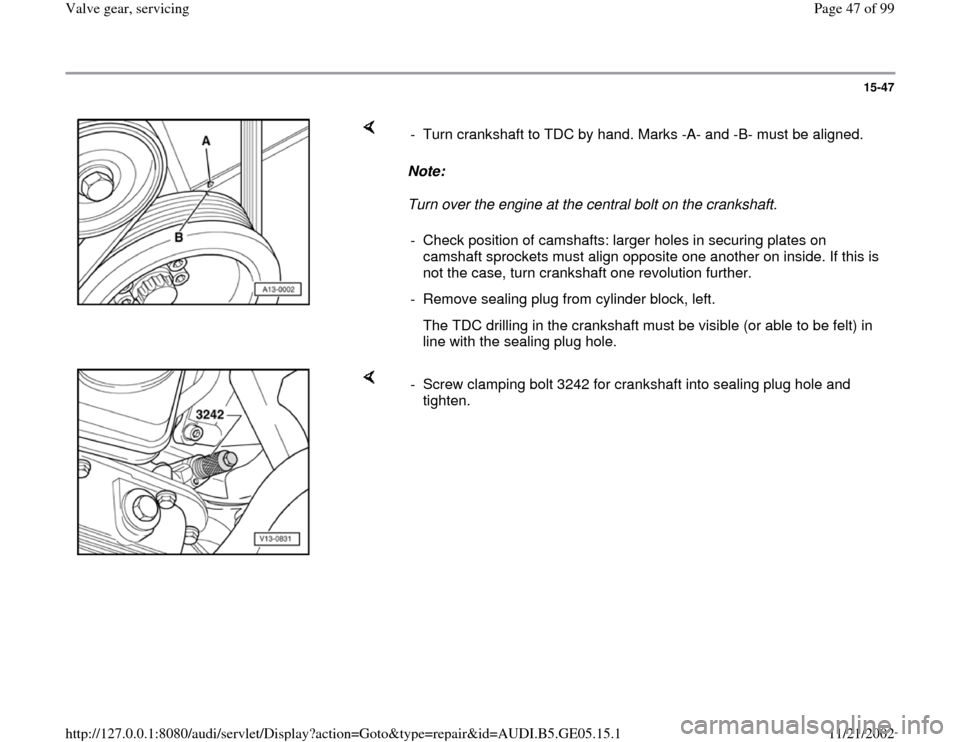
Turn over the engine at the central bolt on the crankshaft. - Turn crankshaft to TDC by hand. Marks -A- and -B- must be aligned.
- Check position of camshafts: larger holes in securing plates on
camshaft sprockets must align opposite one another on inside. If this is
not the case, turn crankshaft one revolution further.
- Remove sealing plug from cylinder block, left.
The TDC drilling in the crankshaft must be visible (or able to be felt) in
line with the sealing plug hole.
- Screw clamping bolt 3242 for crankshaft into sealing plug hole and
tighten.
Pa
ge 47 of 99 Valve
gear, servicin
g
11/21/2002 htt
p://127.0.0.1:8080/audi/servlet/Dis
play?action=Goto&t
yp
e=re
pair&id=AUDI.B5.GE05.15.1
Page 58 of 99
15-58
Compression, checking
Test requirements:
Engine oil temperature at least 30 C.
Battery fully charged.
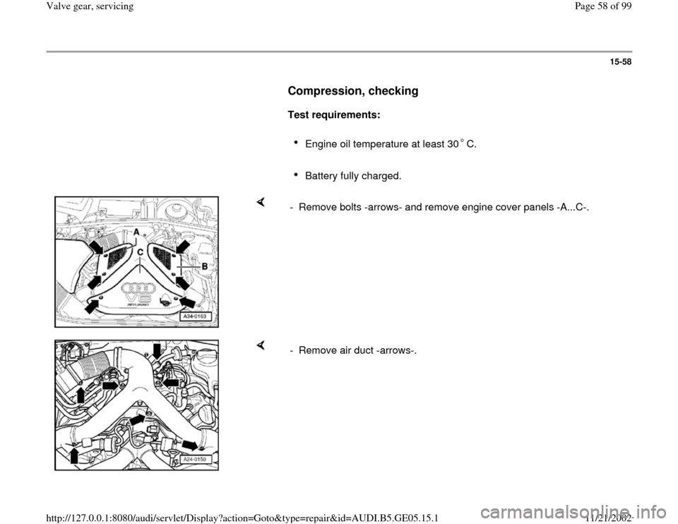
- Remove bolts -arrows- and remove engine cover panels -A...C-.
- Remove air duct -arrows-.
Pa
ge 58 of 99 Valve
gear, servicin
g
11/21/2002 htt
p://127.0.0.1:8080/audi/servlet/Dis
play?action=Goto&t
yp
e=re
pair&id=AUDI.B5.GE05.15.1
Page 67 of 99
15-67
Test sequence
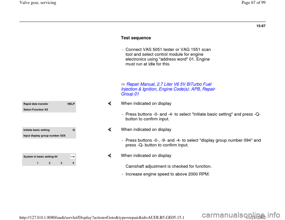
- Connect VAS 5051 tester or VAG 1551 scan
tool and select control module for engine
electronics using "address word" 01. Engine
must run at idle for this.
Repair Manual, 2.7 Liter V6 5V BiTurbo Fuel
Injection & Ignition, Engine Code(s): APB, Repair Group 01
Rapid data transfer
HELP
Select Function XX
When indicated on display
- Press buttons -0- and -4- to select "Initiate basic setting" and press -Q-
button to confirm input.
Initiate basic settin
g
Q
Input display group number XXX
When indicated on display
- Press buttons -0-, -9- and -4- to select "display group number 094" and
press -Q- button to confirm input.
System in basic setting 94
1
2
3
4
When indicated on display
Camshaft adjustment is checked for function.
- Increase engine speed to above 2000 RPM.
Pa
ge 67 of 99 Valve
gear, servicin
g
11/21/2002 htt
p://127.0.0.1:8080/audi/servlet/Dis
play?action=Goto&t
yp
e=re
pair&id=AUDI.B5.GE05.15.1
Page 68 of 99
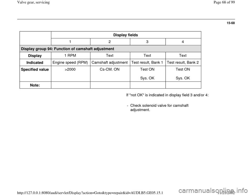
15-68
Display fields
1 2 3 4
Display group 94: Function of camshaft adjustment
Display 1 RPM Text Text Text
Indicated Engine speed (RPM) Camshaft adjustment Test result, Bank 1 Test result, Bank 2
Specified value >2000 Cs-CM. ON Test ON
Sys. OK Test ON
Sys. OK
Note: If "not OK" is indicated in display field 3 and/or 4:
- Check solenoid valve for camshaft
adjustment.
Pa
ge 68 of 99 Valve
gear, servicin
g
11/21/2002 htt
p://127.0.0.1:8080/audi/servlet/Dis
play?action=Goto&t
yp
e=re
pair&id=AUDI.B5.GE05.15.1
Page 70 of 99
15-70
- Initiate output Diagnostic Test Mode (DTM) and
activate the valve for camshaft adjustment.
Repair Manual, 2.7 Liter V6 5V BiTurbo Fuel
Injection & Ignition, Engine Code(s): APB, Repair Group 01
If valves do not click during output Diagnostic
Test Mode (DTM):
Checking internal resistance
- Switch ignition off.
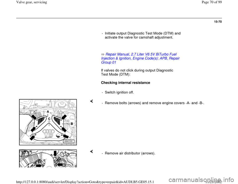
- Remove bolts (arrows) and remove engine covers -A- and -B-.
- Remove air distributor (arrows).
Pa
ge 70 of 99 Valve
gear, servicin
g
11/21/2002 htt
p://127.0.0.1:8080/audi/servlet/Dis
play?action=Goto&t
yp
e=re
pair&id=AUDI.B5.GE05.15.1
Page 71 of 99
15-71
- Disconnect connector from solenoid valve.
If specified value is not obtained:
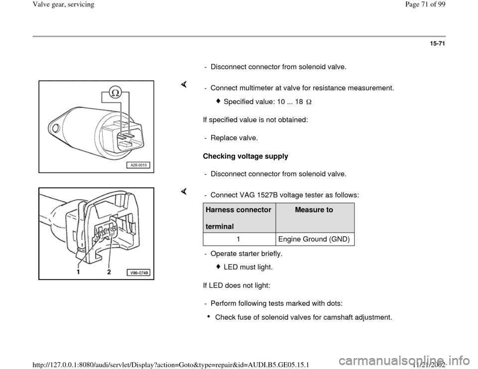
Checking voltage supply - Connect multimeter at valve for resistance measurement.
Specified value: 10 ... 18
- Replace valve.
- Disconnect connector from solenoid valve.
If LED does not light: - Connect VAG 1527B voltage tester as follows:Harness connector
terminal
Measure to
1 Engine Ground (GND)
- Operate starter briefly.
LED must light.
- Perform following tests marked with dots:
Check fuse of solenoid valves for camshaft adjustment.
Pa
ge 71 of 99 Valve
gear, servicin
g
11/21/2002 htt
p://127.0.0.1:8080/audi/servlet/Dis
play?action=Goto&t
yp
e=re
pair&id=AUDI.B5.GE05.15.1
Page 73 of 99
15-72
Electrical Wiring Diagrams, Troubleshooting & Component Locations
If no malfunctions are detected:
Repair Manual, 2.7 Liter V6 5V BiTurbo Fuel Injection & Ignition,
Engine Code(s): APB, Repair Group 24
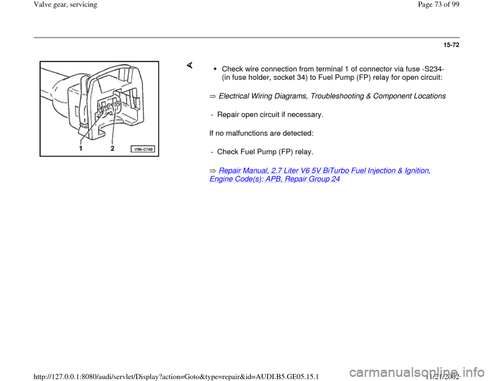
Check wire connection from terminal 1 of connector via fuse -S234-
(in fuse holder, socket 34) to Fuel Pump (FP) relay for open circuit:
- Repair open circuit if necessary.
- Check Fuel Pump (FP) relay.
Pa
ge 73 of 99 Valve
gear, servicin
g
11/21/2002 htt
p://127.0.0.1:8080/audi/servlet/Dis
play?action=Goto&t
yp
e=re
pair&id=AUDI.B5.GE05.15.1
Page 74 of 99
15-73
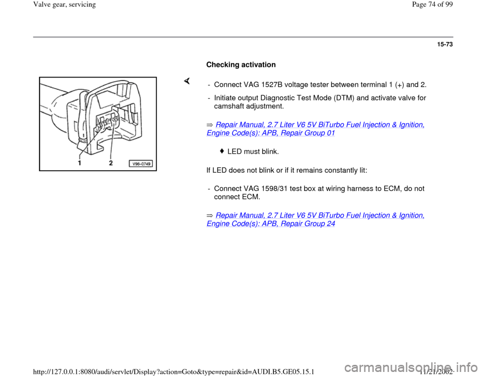
Checking activation
Repair Manual, 2.7 Liter V6 5V BiTurbo Fuel Injection & Ignition,
Engine Code(s): APB, Repair Group 01
If LED does not blink or if it remains constantly lit:
Repair Manual, 2.7 Liter V6 5V BiTurbo Fuel Injection & Ignition,
Engine Code(s): APB, Repair Group 24
- Connect VAG 1527B voltage tester between terminal 1 (+) and 2.
- Initiate output Diagnostic Test Mode (DTM) and activate valve for
camshaft adjustment.
LED must blink.
- Connect VAG 1598/31 test box at wiring harness to ECM, do not
connect ECM.
Pa
ge 74 of 99 Valve
gear, servicin
g
11/21/2002 htt
p://127.0.0.1:8080/audi/servlet/Dis
play?action=Goto&t
yp
e=re
pair&id=AUDI.B5.GE05.15.1
Page 75 of 99
15-74
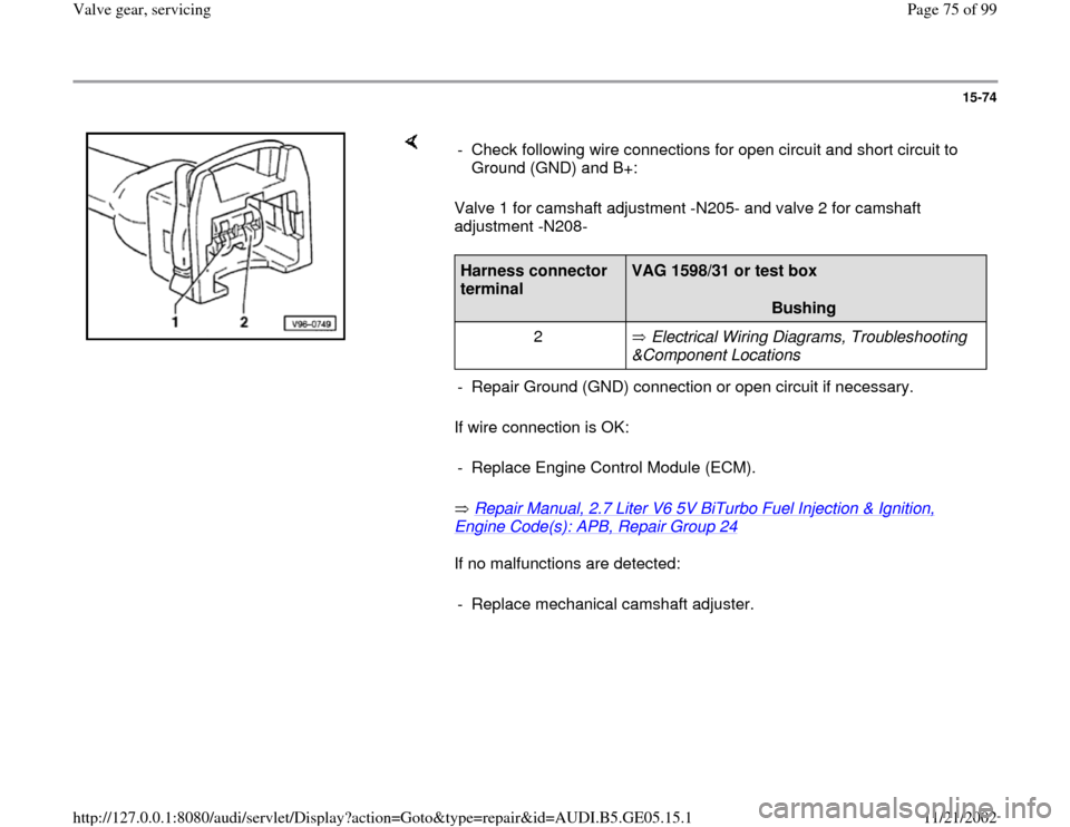
Valve 1 for camshaft adjustment -N205- and valve 2 for camshaft
adjustment -N208-
If wire connection is OK:
Repair Manual, 2.7 Liter V6 5V BiTurbo Fuel Injection & Ignition, Engine Code(s): APB, Repair Group 24
If no malfunctions are detected: - Check following wire connections for open circuit and short circuit to
Ground (GND) and B+:
Harness connector
terminal
VAG 1598/31 or test box
Bushing
2 Electrical Wiring Diagrams, Troubleshooting
&Component Locations
- Repair Ground (GND) connection or open circuit if necessary.
- Replace Engine Control Module (ECM).- Replace mechanical camshaft adjuster.
Pa
ge 75 of 99 Valve
gear, servicin
g
11/21/2002 htt
p://127.0.0.1:8080/audi/servlet/Dis
play?action=Goto&t
yp
e=re
pair&id=AUDI.B5.GE05.15.1