ignition AUDI A4 1997 B5 / 1.G ATW Engine Ignition System User Guide
[x] Cancel search | Manufacturer: AUDI, Model Year: 1997, Model line: A4, Model: AUDI A4 1997 B5 / 1.GPages: 59, PDF Size: 0.53 MB
Page 15 of 59
28-14
Note:
The motronic Engine Control Module (ECM)
power supply relay -J271- supplies voltage to the
ignition coils with power output stages and the
Engine Control Module (ECM) at pin 121.
Test requirement:
Fuses for engine electronics OK
Electrical Wiring Diagrams, Troubleshooting &
Component Locations
Test sequence
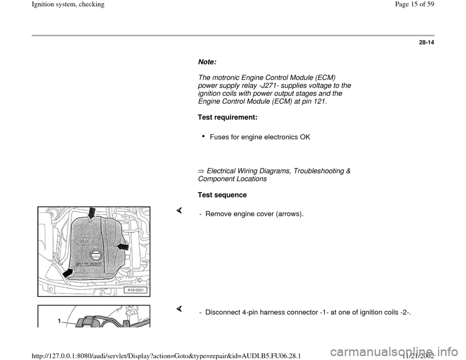
- Remove engine cover (arrows).
- Disconnect 4-pin harness connector -1- at one of ignition coils -2-.
Pa
ge 15 of 59 I
gnition s
ystem, checkin
g
11/21/2002 htt
p://127.0.0.1:8080/audi/servlet/Dis
play?action=Goto&t
yp
e=re
pair&id=AUDI.B5.FU06.28.1
Page 16 of 59
28-15
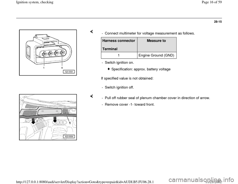
If specified value is not obtained: - Connect multimeter for voltage measurement as follows.Harness connector
Terminal
Measure to
1 Engine Ground (GND)
- Switch ignition on.
Specification: approx. battery voltage
- Switch ignition off.
- Pull off rubber seal of plenum chamber cover in direction of arrow.
- Remove cover -1- toward front.
Pa
ge 16 of 59 I
gnition s
ystem, checkin
g
11/21/2002 htt
p://127.0.0.1:8080/audi/servlet/Dis
play?action=Goto&t
yp
e=re
pair&id=AUDI.B5.FU06.28.1
Page 18 of 59
28-17
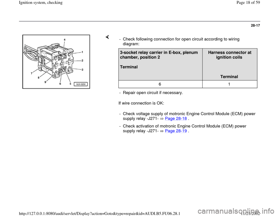
If wire connection is OK: - Check following connection for open circuit according to wiring
diagram: 3-socket relay carrier in E-box, plenum
chamber, position 2
Terminal
Harness connector at
ignition coils
Terminal
6 1
- Repair open circuit if necessary.
- Check voltage supply of motronic Engine Control Module (ECM) power
supply relay -J271- Page 28
-18
.
- Check activation of motronic Engine Control Module (ECM) power
supply relay -J271- Page 28
-19
.
Pa
ge 18 of 59 I
gnition s
ystem, checkin
g
11/21/2002 htt
p://127.0.0.1:8080/audi/servlet/Dis
play?action=Goto&t
yp
e=re
pair&id=AUDI.B5.FU06.28.1
Page 20 of 59
28-19
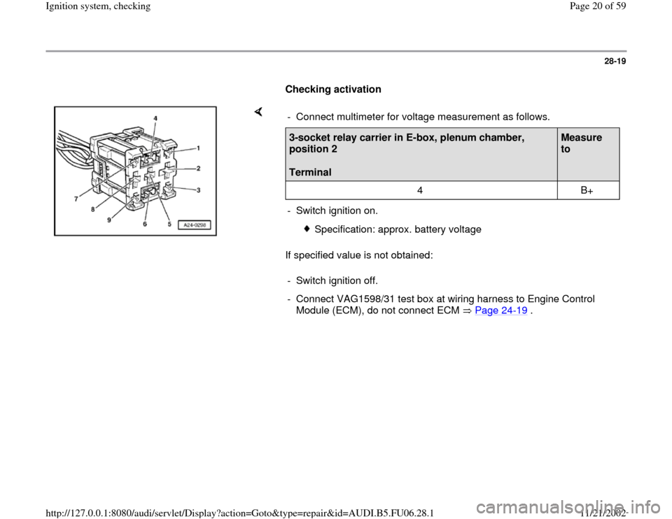
Checking activation
If specified value is not obtained: - Connect multimeter for voltage measurement as follows.3-socket relay carrier in E-box, plenum chamber,
position 2
Terminal
Measure
to
4 B+
- Switch ignition on.
Specification: approx. battery voltage
- Switch ignition off.
- Connect VAG1598/31 test box at wiring harness to Engine Control
Module (ECM), do not connect ECM Page 24
-19
.
Pa
ge 20 of 59 I
gnition s
ystem, checkin
g
11/21/2002 htt
p://127.0.0.1:8080/audi/servlet/Dis
play?action=Goto&t
yp
e=re
pair&id=AUDI.B5.FU06.28.1
Page 38 of 59
28-37
Test requirements:
Fuses for engine electronics OK
Electrical Wiring Diagrams, Troubleshooting &
Component Locations
Battery voltage at least 12.7 V
Generator OK
Test sequence
- Connect VAG1598/31 test box at wiring harness
to Engine Control Module (ECM), do not connect
ECM Page 24
-19
.
- Switch ignition on.
Note:
The plus voltage supply for the Engine Control
Module (ECM) travels via terminal 3 and 121
(terminal 15) as well as terminal 62 (terminal
30).
Pa
ge 38 of 59 I
gnition s
ystem, checkin
g
11/21/2002 htt
p://127.0.0.1:8080/audi/servlet/Dis
play?action=Goto&t
yp
e=re
pair&id=AUDI.B5.FU06.28.1
Page 40 of 59
28-38
- Connect multimeter for voltage measurement as
follows:
VAG1598/31 test box
Socket
Measure to
1 B+
2 B+
62 Engine Ground (GND)
Specification: approx. battery voltage
- Connect multimeter for voltage measurement as
follows:
VAG1598/31 test box
Socket
Measure to
3 Engine Ground (GND)
- Switch ignition on.
Specification: approx. battery voltage
If specified values are not obtained:
Pa
ge 40 of 59 I
gnition s
ystem, checkin
g
11/21/2002 htt
p://127.0.0.1:8080/audi/servlet/Dis
play?action=Goto&t
yp
e=re
pair&id=AUDI.B5.FU06.28.1
Page 42 of 59
28-39
- Connect multimeter for voltage measurement as
follows:
VAG1598/31 test box
Socket
Measure to
121
1)
Engine Ground (GND)
1) The motronic Engine Control Module (ECM)
power supply relay -J271- continues to direct
current to terminal 121 of the Engine Control
Module (ECM) for up to 15 minutes after ignition
is switched off.
- Switch ignition on.
Specification: approx. battery voltage
If specified value is not obtained:
- Check wire connections.
Electrical Wiring Diagrams, Troubleshooting &
Component Locations
-
Check motronic Engine Control Module (ECM)
Pa
ge 42 of 59 I
gnition s
ystem, checkin
g
11/21/2002 htt
p://127.0.0.1:8080/audi/servlet/Dis
play?action=Goto&t
yp
e=re
pair&id=AUDI.B5.FU06.28.1
Page 50 of 59
28-46
Component location Overview of component
locations Page 24
-5
The Camshaft Position (CMP) sensor provides
the ignition position for cylinder 1.
For failure, knock control is switched off and the
ignition angle is retarded slightly since a cylinder
allocation is no longer possible. In addition, the
boost pressure of the turbocharger is decreased.
Engine will continue to run without Camshaft
Position (CMP) sensor signal and can also be
restarted:
When a malfunction is recognized, the Engine
Control Module (ECM) initiates one ignition
spark per cylinder for each crankshaft rotation.
The offset of one engine rotation will have no
noticeable effect on the injection. Instead of
occurring with intake valves open, injection will
be "pre-loaded" (in front of closed intake valve).
This has only a minor effect on the quality of the
mixture preparation.
Pa
ge 50 of 59 I
gnition s
ystem, checkin
g
11/21/2002 htt
p://127.0.0.1:8080/audi/servlet/Dis
play?action=Goto&t
yp
e=re
pair&id=AUDI.B5.FU06.28.1
Page 52 of 59
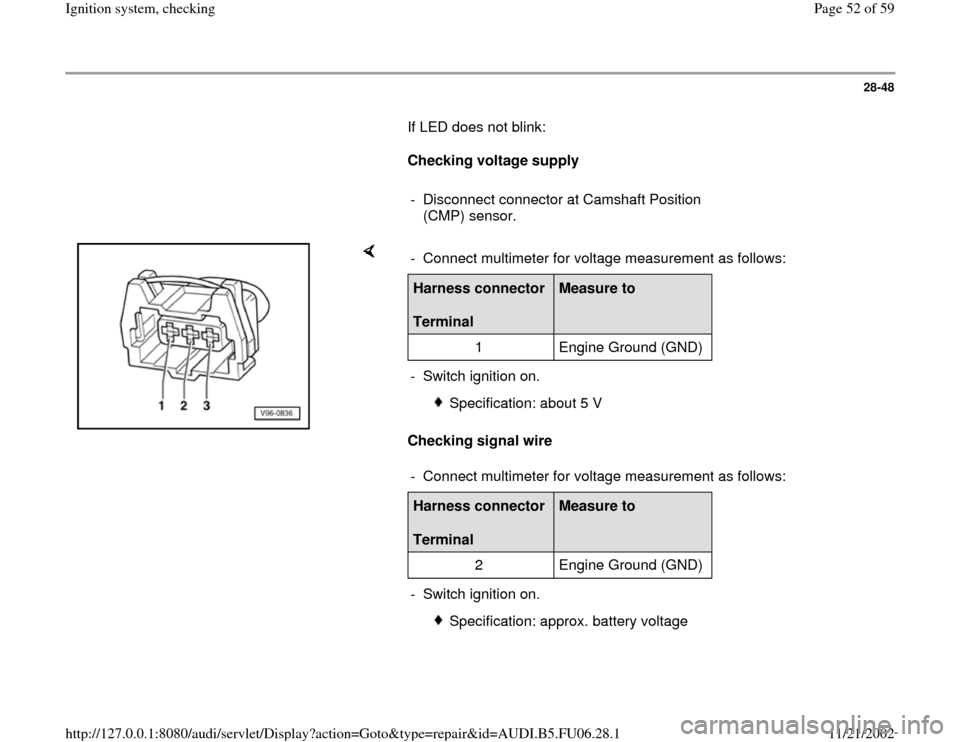
28-48
If LED does not blink:
Checking voltage supply
- Disconnect connector at Camshaft Position
(CMP) sensor.
Checking signal wire - Connect multimeter for voltage measurement as follows:Harness connector
Terminal
Measure to
1 Engine Ground (GND)
- Switch ignition on.
Specification: about 5 V
- Connect multimeter for voltage measurement as follows:
Harness connector
Terminal
Measure to
2 Engine Ground (GND)
- Switch ignition on.
Specification: approx. battery voltage
Pa
ge 52 of 59 I
gnition s
ystem, checkin
g
11/21/2002 htt
p://127.0.0.1:8080/audi/servlet/Dis
play?action=Goto&t
yp
e=re
pair&id=AUDI.B5.FU06.28.1
Page 56 of 59
28-52
Display fields
1 2 3 4
Display group 014: Misfire recognition
Display xxx /min xxx %
xxx
---
Indicated Engine
speed
(RPM) Load
Number of ignition misfires
Misfire recognition
Functional
range
activated
locked
Specified
value xxxx/min 15 to
33 % 0
activated
Note
If the specified value is exceeded:
Check combustion misfires of
individual cylinders Page 28
-53
If ignition misfires are to be expected due to
operation conditions (e.g. warm-up,
deceleration shut-down), misfire recognition
is deactivated
If specified value is obtained:
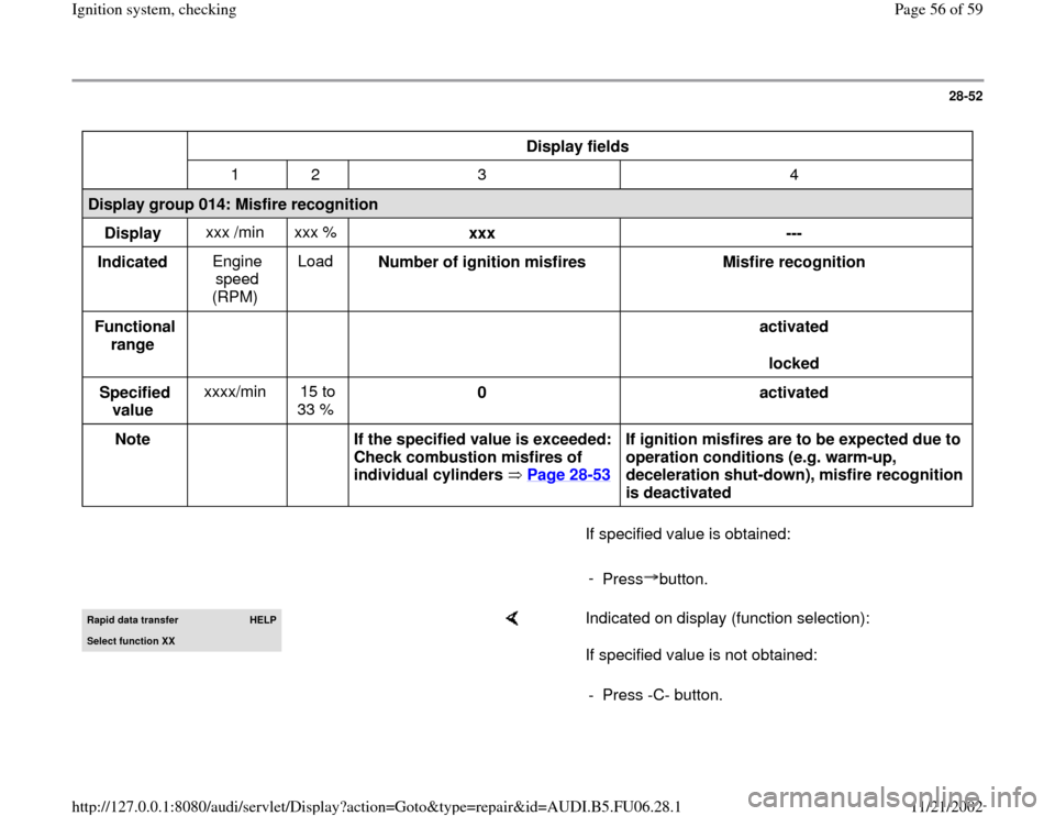
-
Press button.Rapid data transfer
HELP
Select function XX
Indicated on display (function selection):
If specified value is not obtained:
- Press -C- button.
Pa
ge 56 of 59 I
gnition s
ystem, checkin
g
11/21/2002 htt
p://127.0.0.1:8080/audi/servlet/Dis
play?action=Goto&t
yp
e=re
pair&id=AUDI.B5.FU06.28.1