ECU AUDI A4 1997 B5 / 1.G AWM Engine Valve Gear Service Workshop Manual
[x] Cancel search | Manufacturer: AUDI, Model Year: 1997, Model line: A4, Model: AUDI A4 1997 B5 / 1.GPages: 58, PDF Size: 1.06 MB
Page 16 of 58
15-52
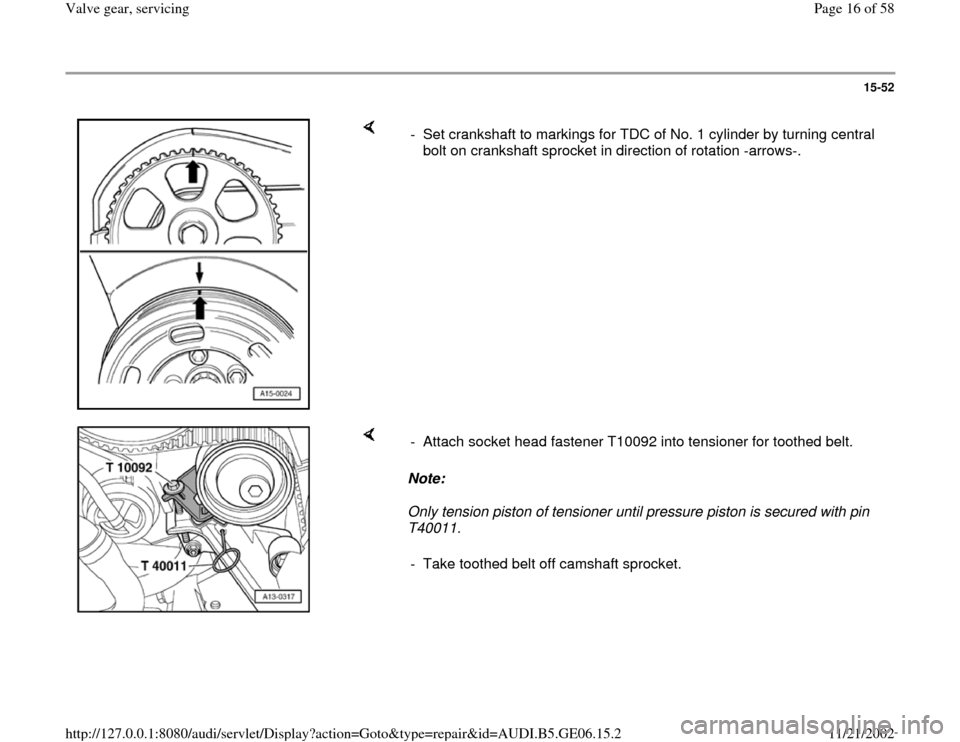
- Set crankshaft to markings for TDC of No. 1 cylinder by turning central
bolt on crankshaft sprocket in direction of rotation -arrows-.
Note:
Only tension piston of tensioner until pressure piston is secured with pin
T40011. - Attach socket head fastener T10092 into tensioner for toothed belt.
- Take toothed belt off camshaft sprocket.
Pa
ge 16 of 58 Valve
gear, servicin
g
11/21/2002 htt
p://127.0.0.1:8080/audi/servlet/Dis
play?action=Goto&t
yp
e=re
pair&id=AUDI.B5.GE06.15.2
Page 17 of 58
15-53
- Loosen camshaft sprocket (counter hold with
3036).
- Remove camshaft sprocket.
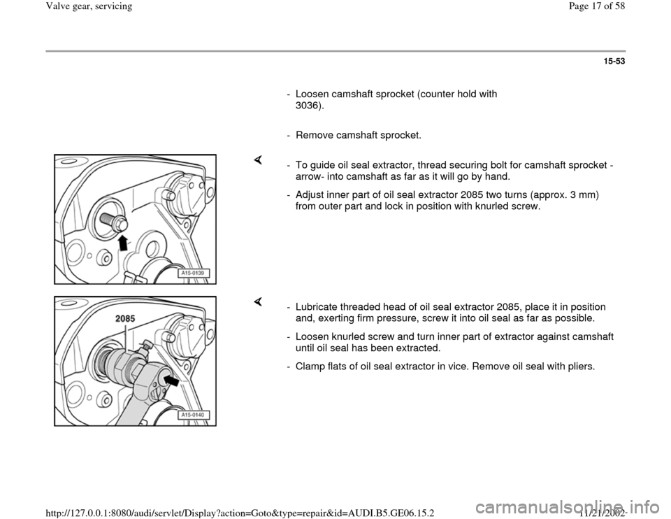
- To guide oil seal extractor, thread securing bolt for camshaft sprocket -
arrow- into camshaft as far as it will go by hand.
- Adjust inner part of oil seal extractor 2085 two turns (approx. 3 mm)
from outer part and lock in position with knurled screw.
- Lubricate threaded head of oil seal extractor 2085, place it in position
and, exerting firm pressure, screw it into oil seal as far as possible.
- Loosen knurled screw and turn inner part of extractor against camshaft
until oil seal has been extracted.
- Clamp flats of oil seal extractor in vice. Remove oil seal with pliers.
Pa
ge 17 of 58 Valve
gear, servicin
g
11/21/2002 htt
p://127.0.0.1:8080/audi/servlet/Dis
play?action=Goto&t
yp
e=re
pair&id=AUDI.B5.GE06.15.2
Page 19 of 58
15-55
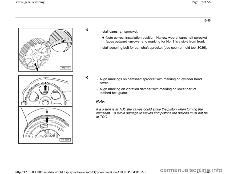
- Install camshaft sprocket.
Note correct installation position: Narrow web of camshaft sprocket
faces outward -arrows- and marking for No. 1 is visible from front.
- Install securing bolt for camshaft sprocket (use counter hold tool 3036).
Note:
If a piston is at TDC the valves could strike the piston when turning the
camshaft. To avoid damage to valves and pistons the pistons must not be
at TDC. - Align markings on camshaft sprocket with marking on cylinder head
cover.
- Align marking on vibration damper with marking on lower part of
toothed belt guard.
Pa
ge 19 of 58 Valve
gear, servicin
g
11/21/2002 htt
p://127.0.0.1:8080/audi/servlet/Dis
play?action=Goto&t
yp
e=re
pair&id=AUDI.B5.GE06.15.2
Page 29 of 58
15-64
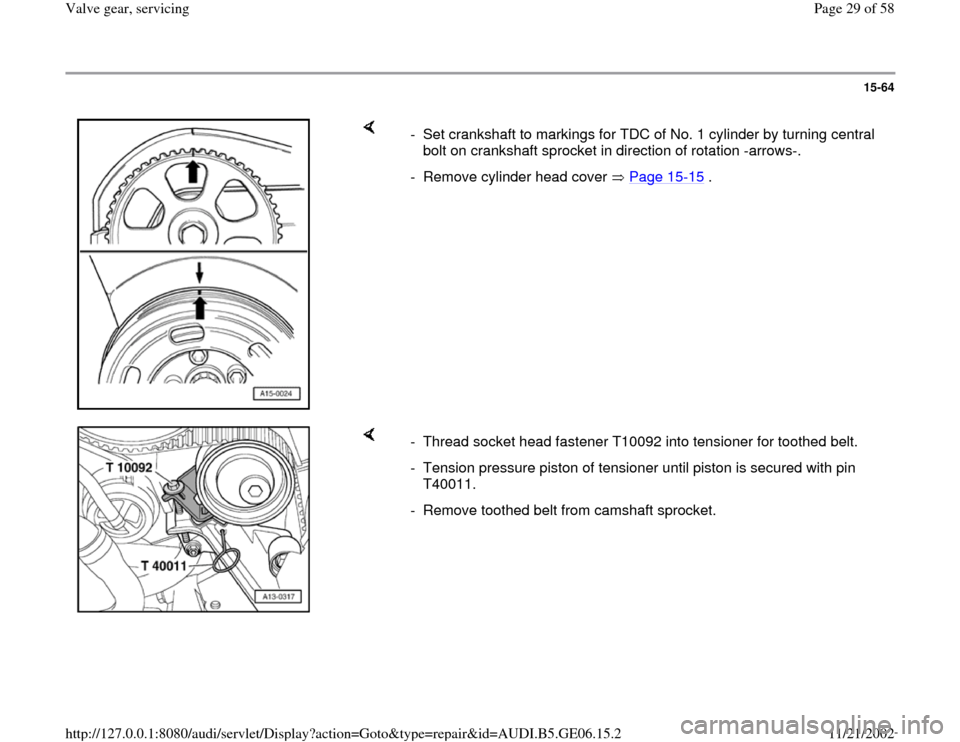
- Set crankshaft to markings for TDC of No. 1 cylinder by turning central
bolt on crankshaft sprocket in direction of rotation -arrows-.
- Remove cylinder head cover Page 15
-15
.
- Thread socket head fastener T10092 into tensioner for toothed belt.
- Tension pressure piston of tensioner until piston is secured with pin
T40011.
- Remove toothed belt from camshaft sprocket.
Pa
ge 29 of 58 Valve
gear, servicin
g
11/21/2002 htt
p://127.0.0.1:8080/audi/servlet/Dis
play?action=Goto&t
yp
e=re
pair&id=AUDI.B5.GE06.15.2
Page 31 of 58
15-66
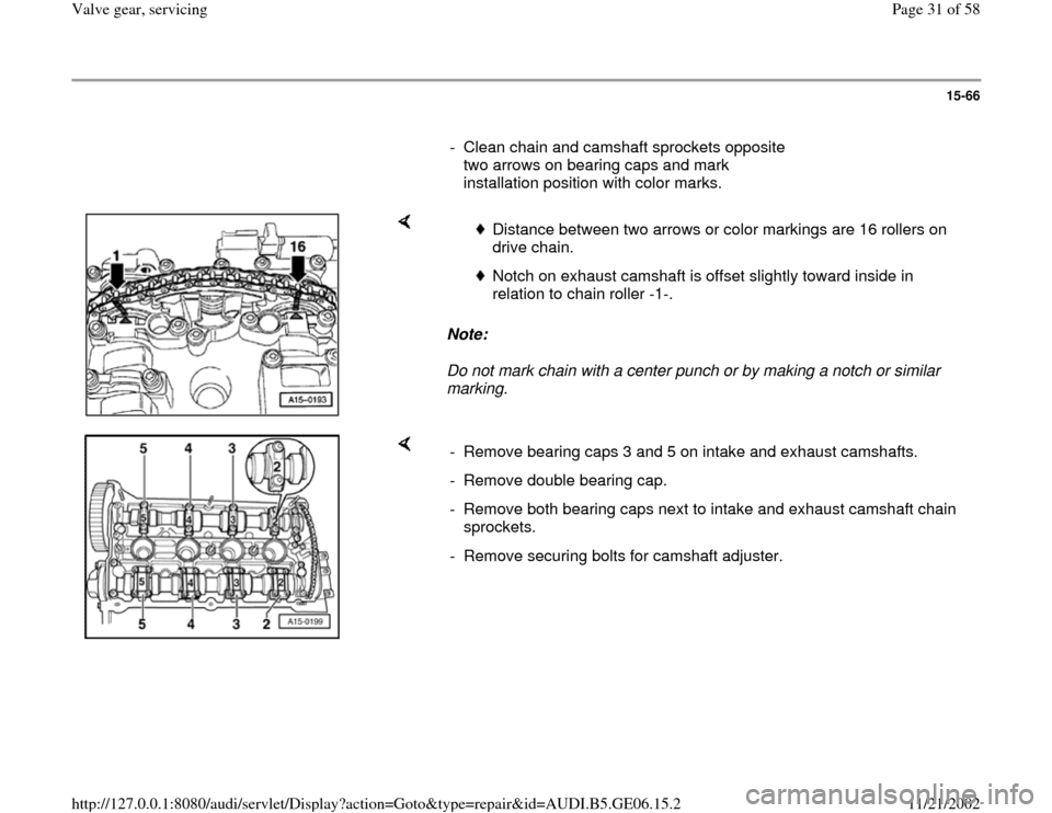
- Clean chain and camshaft sprockets opposite
two arrows on bearing caps and mark
installation position with color marks.
Note:
Do not mark chain with a center punch or by making a notch or similar
marking.
Distance between two arrows or color markings are 16 rollers on
drive chain.
Notch on exhaust camshaft is offset slightly toward inside in
relation to chain roller -1-.
- Remove bearing caps 3 and 5 on intake and exhaust camshafts.
- Remove double bearing cap.
- Remove both bearing caps next to intake and exhaust camshaft chain
sprockets.
- Remove securing bolts for camshaft adjuster.
Pa
ge 31 of 58 Valve
gear, servicin
g
11/21/2002 htt
p://127.0.0.1:8080/audi/servlet/Dis
play?action=Goto&t
yp
e=re
pair&id=AUDI.B5.GE06.15.2
Page 36 of 58
15-71
- Remove holder for chain tensioner 3366.
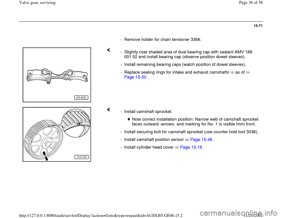
- Slightly coat shaded area of dual bearing cap with sealant AMV 188
001 02 and install bearing cap (observe position dowel sleeves).
- Install remaining bearing caps (watch position of dowel sleeves).
- Replace sealing rings for intake and exhaust camshafts as of
Page 15
-50
.
- Install camshaft sprocket.
Note correct installation position: Narrow web of camshaft sprocket
faces outward -arrows- and marking for No. 1 is visible from front.
- Install securing bolt for camshaft sprocket (use counter hold tool 3036).
- Install camshaft position sensor Page 15
-46
.
- Install cylinder head cover Page 15
-18
.
Pa
ge 36 of 58 Valve
gear, servicin
g
11/21/2002 htt
p://127.0.0.1:8080/audi/servlet/Dis
play?action=Goto&t
yp
e=re
pair&id=AUDI.B5.GE06.15.2
Page 39 of 58
15-74
Hydraulic valve lifters, checking
Special tools and equipment
Feeler gauge
Wood or plastic wedge
Note:
Hydraulic valve lifters cannot be adjusted or
repaired.
Irregular valve noise during starting is normal.
Test sequence
- Start engine and let run until coolant
temperature has reached approx. 80 C.
- Increase engine speed to about 2500 rpm for 2
minutes (perform road test if necessary).
Note:
If the irregular valve noises stop but recur
repeatedly during short journeys, a new oil
retention valve must be fitted. Oil retention valve
location: In oil filter bracket -Item 6 -, Page
Pa
ge 39 of 58 Valve
gear, servicin
g
11/21/2002 htt
p://127.0.0.1:8080/audi/servlet/Dis
play?action=Goto&t
yp
e=re
pair&id=AUDI.B5.GE06.15.2