light AUDI A4 1997 B5 / 1.G AWM Engine Valve Gear Service Workshop Manual
[x] Cancel search | Manufacturer: AUDI, Model Year: 1997, Model line: A4, Model: AUDI A4 1997 B5 / 1.GPages: 58, PDF Size: 1.06 MB
Page 6 of 58
15-42
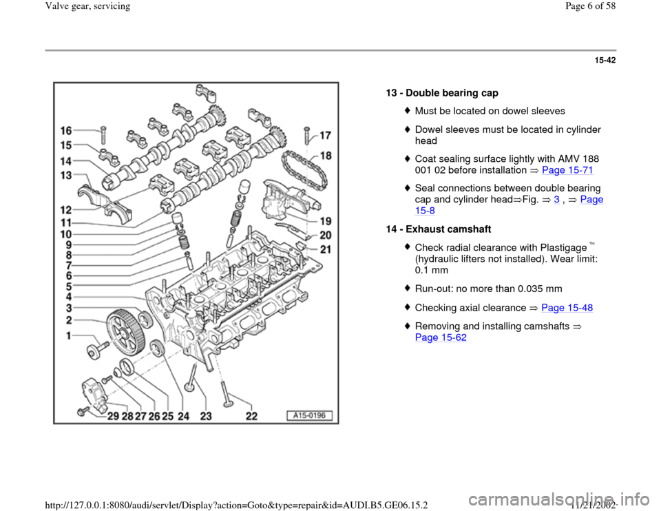
13 -
Double bearing cap
Must be located on dowel sleevesDowel sleeves must be located in cylinder
head Coat sealing surface lightly with AMV 188
001 02 before installation Page 15
-71
Seal connections between double bearing
cap and cylinder head Fig. 3
, Page
15
-8
14 -
Exhaust camshaft
Check radial clearance with Plastigage
(hydraulic lifters not installed). Wear limit:
0.1 mm Run-out: no more than 0.035 mmChecking axial clearance Page 15
-48
Removing and installing camshafts
Page 15
-62
Pa
ge 6 of 58 Valve
gear, servicin
g
11/21/2002 htt
p://127.0.0.1:8080/audi/servlet/Dis
play?action=Goto&t
yp
e=re
pair&id=AUDI.B5.GE06.15.2
Page 8 of 58
15-44
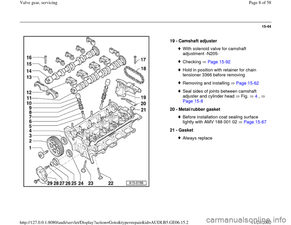
19 -
Camshaft adjuster
With solenoid valve for camshaft
adjustment -N205- Checking Page 15
-92
Hold in position with retainer for chain
tensioner 3366 before removing Removing and installing Page 15
-62
Seal sides of joints between camshaft
adjuster and cylinder head Fig. 4
,
Page 15
-8
20 -
Metal/rubber gasket
Before installation coat sealing surface
lightly with AMV 188 001 02 Page 15
-67
21 -
Gasket
Always replace
Pa
ge 8 of 58 Valve
gear, servicin
g
11/21/2002 htt
p://127.0.0.1:8080/audi/servlet/Dis
play?action=Goto&t
yp
e=re
pair&id=AUDI.B5.GE06.15.2
Page 31 of 58
15-66
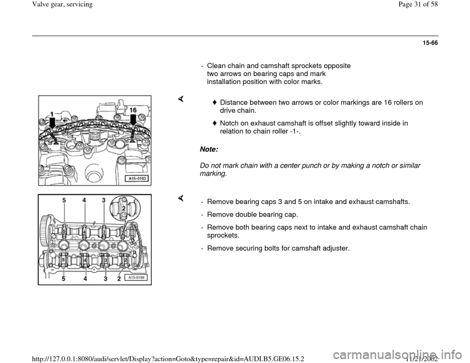
- Clean chain and camshaft sprockets opposite
two arrows on bearing caps and mark
installation position with color marks.
Note:
Do not mark chain with a center punch or by making a notch or similar
marking.
Distance between two arrows or color markings are 16 rollers on
drive chain.
Notch on exhaust camshaft is offset slightly toward inside in
relation to chain roller -1-.
- Remove bearing caps 3 and 5 on intake and exhaust camshafts.
- Remove double bearing cap.
- Remove both bearing caps next to intake and exhaust camshaft chain
sprockets.
- Remove securing bolts for camshaft adjuster.
Pa
ge 31 of 58 Valve
gear, servicin
g
11/21/2002 htt
p://127.0.0.1:8080/audi/servlet/Dis
play?action=Goto&t
yp
e=re
pair&id=AUDI.B5.GE06.15.2
Page 33 of 58
15-68
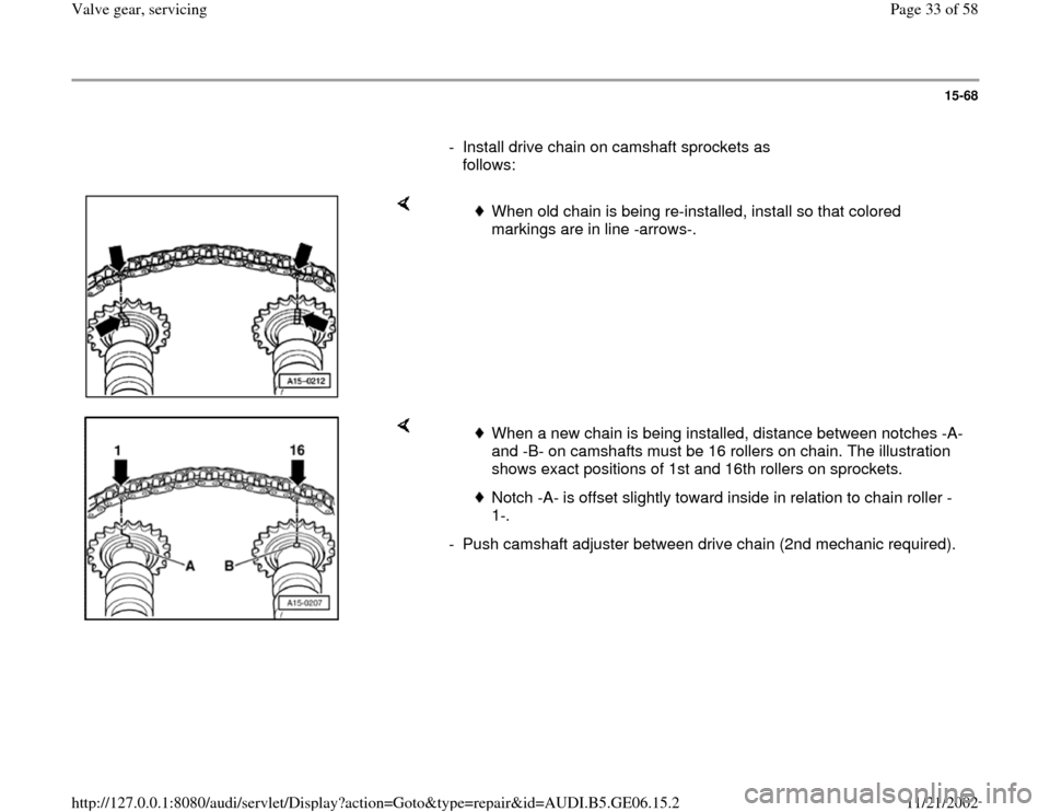
- Install drive chain on camshaft sprockets as
follows:
When old chain is being re-installed, install so that colored
markings are in line -arrows-.
When a new chain is being installed, distance between notches -A-
and -B- on camshafts must be 16 rollers on chain. The illustration
shows exact positions of 1st and 16th rollers on sprockets.
Notch -A- is offset slightly toward inside in relation to chain roller -
1-.
- Push camshaft adjuster between drive chain (2nd mechanic required).
Pa
ge 33 of 58 Valve
gear, servicin
g
11/21/2002 htt
p://127.0.0.1:8080/audi/servlet/Dis
play?action=Goto&t
yp
e=re
pair&id=AUDI.B5.GE06.15.2
Page 35 of 58
15-70
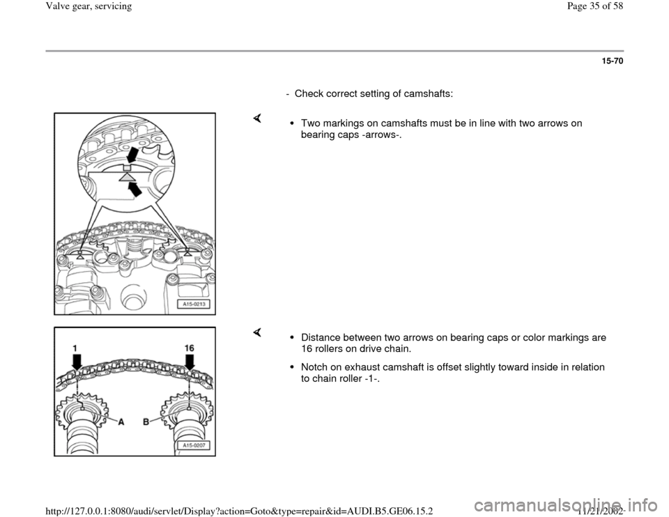
- Check correct setting of camshafts:
Two markings on camshafts must be in line with two arrows on
bearing caps -arrows-.
Distance between two arrows on bearing caps or color markings are
16 rollers on drive chain. Notch on exhaust camshaft is offset slightly toward inside in relation
to chain roller -1-.
Pa
ge 35 of 58 Valve
gear, servicin
g
11/21/2002 htt
p://127.0.0.1:8080/audi/servlet/Dis
play?action=Goto&t
yp
e=re
pair&id=AUDI.B5.GE06.15.2
Page 36 of 58
15-71
- Remove holder for chain tensioner 3366.
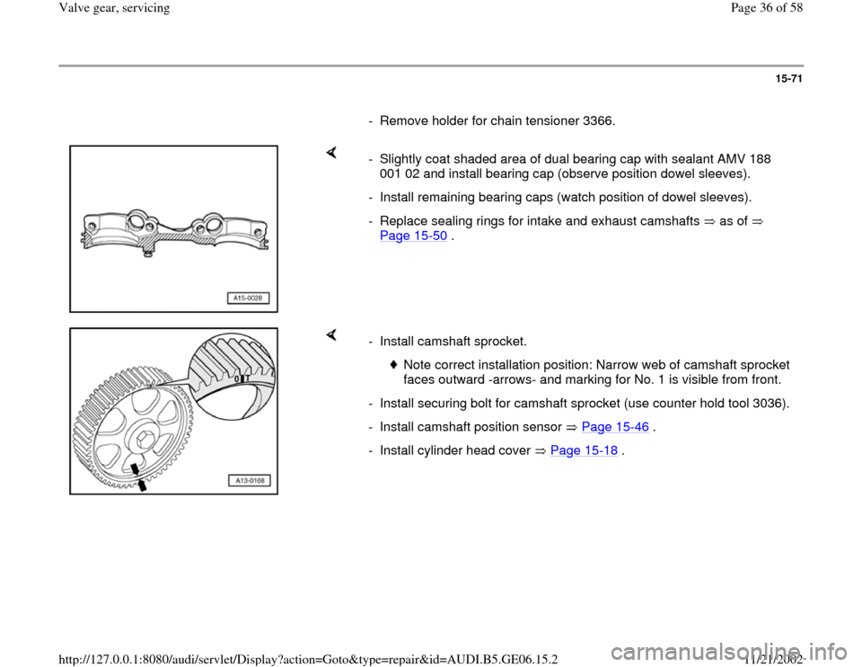
- Slightly coat shaded area of dual bearing cap with sealant AMV 188
001 02 and install bearing cap (observe position dowel sleeves).
- Install remaining bearing caps (watch position of dowel sleeves).
- Replace sealing rings for intake and exhaust camshafts as of
Page 15
-50
.
- Install camshaft sprocket.
Note correct installation position: Narrow web of camshaft sprocket
faces outward -arrows- and marking for No. 1 is visible from front.
- Install securing bolt for camshaft sprocket (use counter hold tool 3036).
- Install camshaft position sensor Page 15
-46
.
- Install cylinder head cover Page 15
-18
.
Pa
ge 36 of 58 Valve
gear, servicin
g
11/21/2002 htt
p://127.0.0.1:8080/audi/servlet/Dis
play?action=Goto&t
yp
e=re
pair&id=AUDI.B5.GE06.15.2
Page 46 of 58
15-80
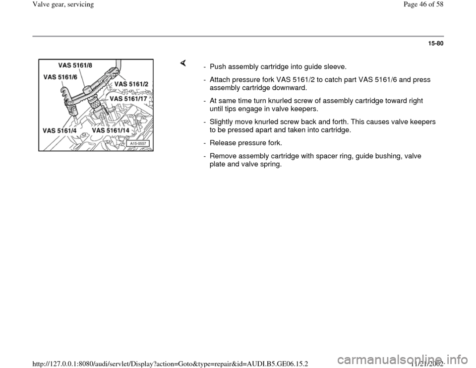
- Push assembly cartridge into guide sleeve.
- Attach pressure fork VAS 5161/2 to catch part VAS 5161/6 and press
assembly cartridge downward.
- At same time turn knurled screw of assembly cartridge toward right
until tips engage in valve keepers.
- Slightly move knurled screw back and forth. This causes valve keepers
to be pressed apart and taken into cartridge.
- Release pressure fork.
- Remove assembly cartridge with spacer ring, guide bushing, valve
plate and valve spring.
Pa
ge 46 of 58 Valve
gear, servicin
g
11/21/2002 htt
p://127.0.0.1:8080/audi/servlet/Dis
play?action=Goto&t
yp
e=re
pair&id=AUDI.B5.GE06.15.2
Page 47 of 58
15-81
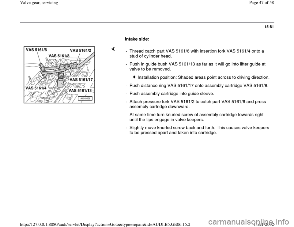
Intake side:
- Thread catch part VAS 5161/6 with insertion fork VAS 5161/4 onto a
stud of cylinder head.
- Push in guide bush VAS 5161/13 as far as it will go into lifter guide at
valve to be removed.
Installation position: Shaded areas point across to driving direction.
- Push distance ring VAS 5161/17 onto assembly cartridge VAS 5161/8.
- Push assembly cartridge into guide sleeve.
- Attach pressure fork VAS 5161/2 to catch part VAS 5161/6 and press
assembly cartridge downward.
- At same time turn knurled screw of assembly cartridge towards right
until the tips engage in valve keepers.
- Slightly move knurled screw back and forth. This causes valve keepers
to be pressed apart and taken into cartridge.
Pa
ge 47 of 58 Valve
gear, servicin
g
11/21/2002 htt
p://127.0.0.1:8080/audi/servlet/Dis
play?action=Goto&t
yp
e=re
pair&id=AUDI.B5.GE06.15.2
Page 49 of 58
15-83
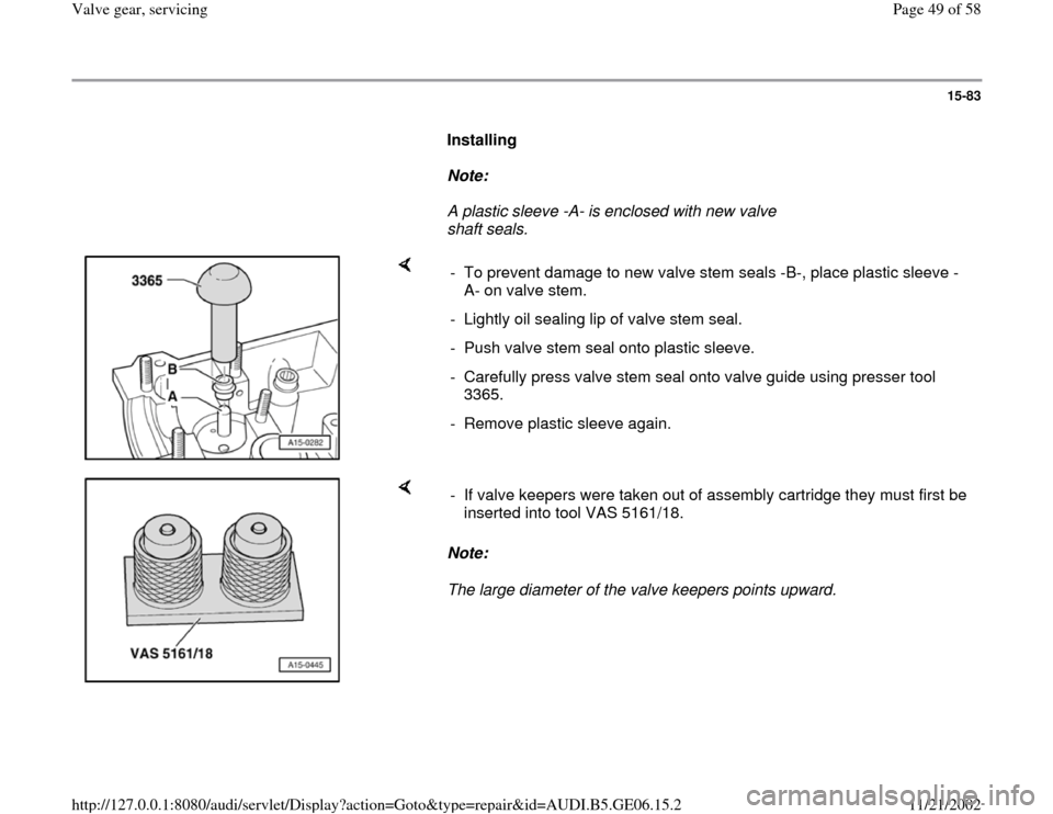
Installing
Note:
A plastic sleeve -A- is enclosed with new valve
shaft seals.
- To prevent damage to new valve stem seals -B-, place plastic sleeve -
A- on valve stem.
- Lightly oil sealing lip of valve stem seal.
- Push valve stem seal onto plastic sleeve.
- Carefully press valve stem seal onto valve guide using presser tool
3365.
- Remove plastic sleeve again.
Note:
The large diameter of the valve keepers points upward. - If valve keepers were taken out of assembly cartridge they must first be
inserted into tool VAS 5161/18.
Pa
ge 49 of 58 Valve
gear, servicin
g
11/21/2002 htt
p://127.0.0.1:8080/audi/servlet/Dis
play?action=Goto&t
yp
e=re
pair&id=AUDI.B5.GE06.15.2
Page 52 of 58
15-86
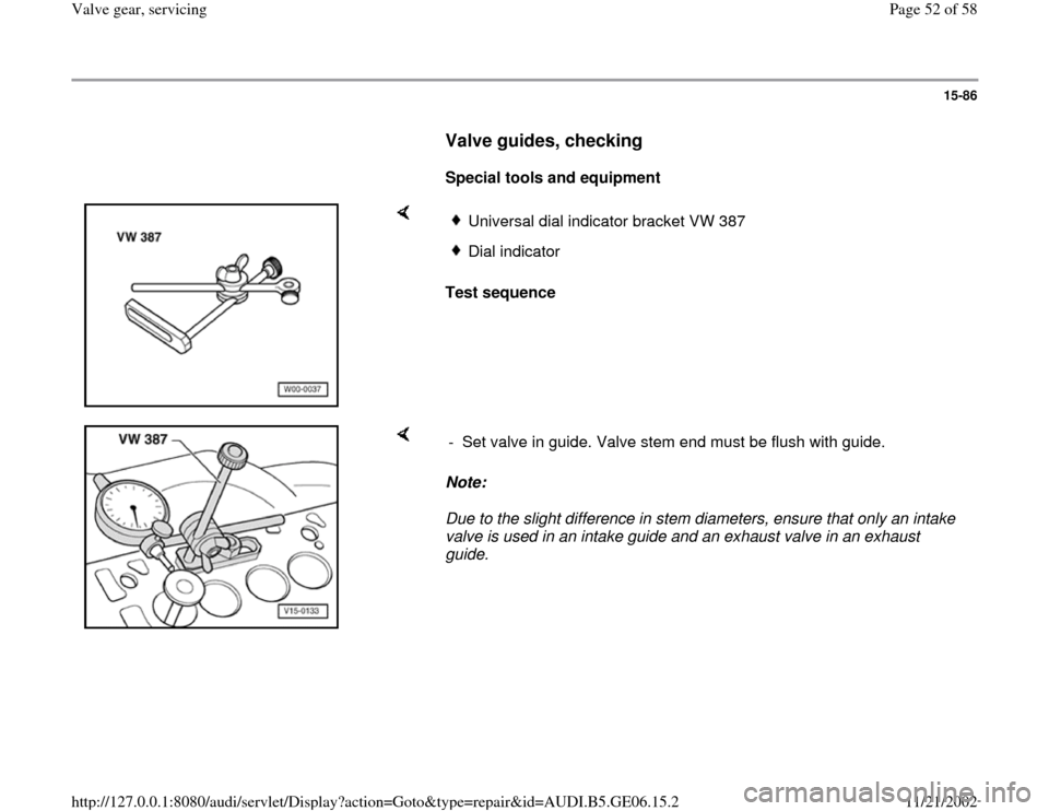
Valve guides, checking
Special tools and equipment
Test sequence
Universal dial indicator bracket VW 387Dial indicator
Note:
Due to the slight difference in stem diameters, ensure that only an intake
valve is used in an intake guide and an exhaust valve in an exhaust
guide. - Set valve in guide. Valve stem end must be flush with guide.
Pa
ge 52 of 58 Valve
gear, servicin
g
11/21/2002 htt
p://127.0.0.1:8080/audi/servlet/Dis
play?action=Goto&t
yp
e=re
pair&id=AUDI.B5.GE06.15.2