manual transmission AUDI A4 1997 B5 / 1.G Brakes Read Mesure Value Block Workshop Manual
[x] Cancel search | Manufacturer: AUDI, Model Year: 1997, Model line: A4, Model: AUDI A4 1997 B5 / 1.GPages: 79, PDF Size: 0.24 MB
Page 3 of 79

01-63
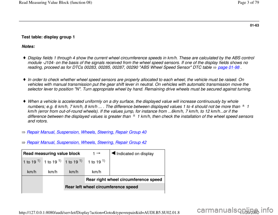
Test table: display group 1
Notes:
Display fields 1 through 4 show the current wheel circumference speeds in km/h. These are calculated by the ABS control
module -J104- on the basis of the signals received from the wheel speed sensors. If one of the display fields shows no
reading, proceed as for DTCs 00283, 00285, 00287, 00290 "ABS Wheel Speed Sensor" DTC table page 01
-98
.
In order to check whether wheel speed sensors are properly allocated to each wheel, the vehicle must be raised. On
vehicles with manual transmission put the gear shift lever in neutral. On vehicles with automatic transmission move the
selector lever to position "N". Turn appropriate wheel by hand. Remaining drive wheels must be secured against turning.
When a vehicle is accelerated uniformly on a dry surface, the displayed value will increase continuously by whole
numbers; e.g. 6 km/h, 7 km/h, 8 km/h ... . The difference between displayed values 1 to 4 should not be more than 1
km/h (error from out-of-round wheels). If the values jump, for instance from ...6km/h, 7 km/h, to 12 km/h...or if the
difference between the displayed values is greater than 1 km/h, then check the installation of the wheel speed sensors
and rotors. Repair Manual, Suspension, Wheels, Steering, Repair Group 40
Repair Manual, Suspension, Wheels, Steering, Repair Group 42
Read measuring value block
1
Indicated on display
1 to 19
1)
km/h 1 to 19
1)
km/h
1 to 19
1)
km/h 1 to 19
1)
km/h
Rear right wheel circumference speed
Rear left wheel circumference speed
Pa
ge 3 of 79 Read Measurin
g Value Block
(function 08
)
11/20/2002 htt
p://127.0.0.1:8080/audi/servlet/Dis
play?action=Goto&t
yp
e=re
pair&id=AUDI.B5.SU02.01.8
Page 12 of 79

01-69
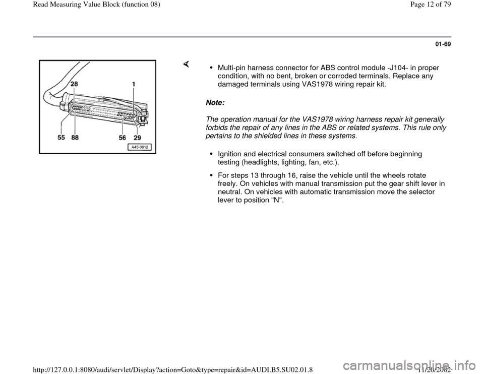
Note:
The operation manual for the VAS1978 wiring harness repair kit generally
forbids the repair of any lines in the ABS or related systems. This rule only
pertains to the shielded lines in these systems.
Multi-pin harness connector for ABS control module -J104- in proper
condition, with no bent, broken or corroded terminals. Replace any
damaged terminals using VAS1978 wiring repair kit. Ignition and electrical consumers switched off before beginning
testing (headlights, lighting, fan, etc.). For steps 13 through 16, raise the vehicle until the wheels rotate
freely. On vehicles with manual transmission put the gear shift lever in
neutral. On vehicles with automatic transmission move the selector
lever to position "N".
Pa
ge 12 of 79 Read Measurin
g Value Block
(function 08
)
11/20/2002 htt
p://127.0.0.1:8080/audi/servlet/Dis
play?action=Goto&t
yp
e=re
pair&id=AUDI.B5.SU02.01.8
Page 46 of 79

01-91
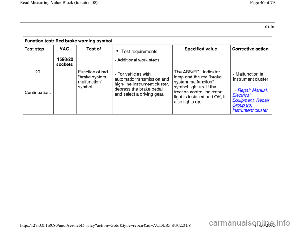
Function test: Red brake warning symbol
Test step
VAG
1598/20
sockets Test of
Test requirements
- Additional work stepsSpecified value
Corrective action
20
Continuation: Function of red
"brake system
malfunction"
symbol - For vehicles with
automatic transmission and
high-line instrument cluster,
depress the brake pedal
and select a driving gear. The ABS/EDL indicator
lamp and the red "brake
system malfunction"
symbol light up. If the
traction control indicator
light is installed and OK, it
also lights up. Repair Manual,
Electrical Equipment, Repair Group 90; Instrument cluster
- Malfunction in
instrument cluster
Pa
ge 46 of 79 Read Measurin
g Value Block
(function 08
)
11/20/2002 htt
p://127.0.0.1:8080/audi/servlet/Dis
play?action=Goto&t
yp
e=re
pair&id=AUDI.B5.SU02.01.8
Page 72 of 79

01-113
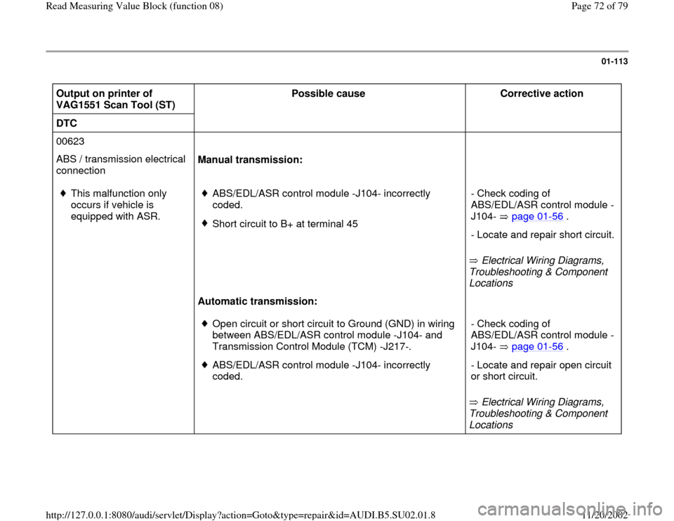
Output on printer of
VAG1551 Scan Tool (ST) Possible cause
Corrective action
DTC
00623
ABS / transmission electrical
connection Manual transmission:
This malfunction only
occurs if vehicle is
equipped with ASR.
ABS/EDL/ASR control module -J104- incorrectly
coded. Short circuit to B+ at terminal 45
Electrical Wiring Diagrams,
Troubleshooting & Component
Locations - Check coding of
ABS/EDL/ASR control module -
J104- page 01
-56
.
- Locate and repair short circuit.
Automatic transmission:
Open circuit or short circuit to Ground (GND) in wiring
between ABS/EDL/ASR control module -J104- and
Transmission Control Module (TCM) -J217-. ABS/EDL/ASR control module -J104- incorrectly
coded.
Electrical Wiring Diagrams,
Troubleshooting & Component
Locations - Check coding of
ABS/EDL/ASR control module -
J104- page 01
-56
.
- Locate and repair open circuit
or short circuit.
Pa
ge 72 of 79 Read Measurin
g Value Block
(function 08
)
11/20/2002 htt
p://127.0.0.1:8080/audi/servlet/Dis
play?action=Goto&t
yp
e=re
pair&id=AUDI.B5.SU02.01.8