warning AUDI A4 1997 B5 / 1.G Brakes Read Mesure Value Block Workshop Manual
[x] Cancel search | Manufacturer: AUDI, Model Year: 1997, Model line: A4, Model: AUDI A4 1997 B5 / 1.GPages: 79, PDF Size: 0.24 MB
Page 9 of 79
01-67
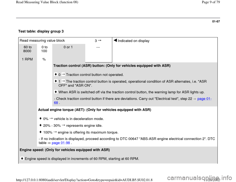
Test table: display group 3 Read measuring value block
3
Indicated on display
60 to
8000
1 RPM 0 to
100
%
0 or 1
---
Traction control (ASR) button: (Only for vehicles equipped with ASR)
0 Traction control button not operated. 1 The traction control button is operated, operational condition of ASR alternates, i.e. "ASR
OFF" and "ASR ON". When ASR is switched off via the traction control button, the warning lamp for ASR lights up.
- Check traction control button if there are deviations. Carry out "Electrical test", step 22 page 01
-
68
.
Actual engine torque (AET): (Only for vehicles equipped with ASR)
0% vehicle is in deceleration mode.20% - 30% represents engine idle.100% engine is offering its maximum torque.
- If no indication is displayed, proceed according to DTC 00647 "ABS-ASR engine electrical connection 2". DTC
table page 01
-98
.
Engine speed: (Only for vehicles equipped with ASR)
Engine speed is displayed in increments of 60 RPM, starting at 60 RPM.
Pa
ge 9 of 79 Read Measurin
g Value Block
(function 08
)
11/20/2002 htt
p://127.0.0.1:8080/audi/servlet/Dis
play?action=Goto&t
yp
e=re
pair&id=AUDI.B5.SU02.01.8
Page 17 of 79
01-73
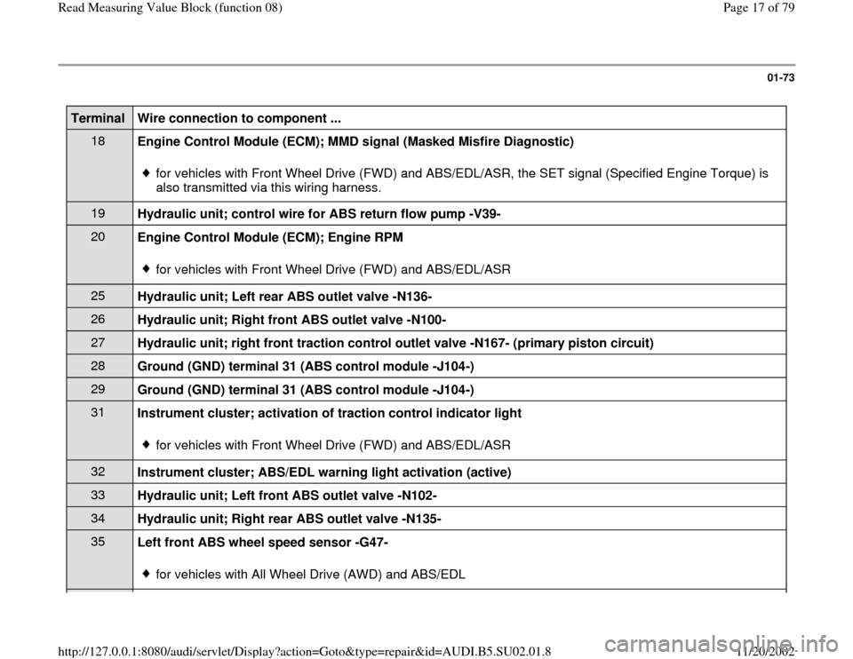
Terminal
Wire connection to component ...
18
Engine Control Module (ECM); MMD signal (Masked Misfire Diagnostic)
for vehicles with Front Wheel Drive (FWD) and ABS/EDL/ASR, the SET signal (Specified Engine Torque) is
also transmitted via this wiring harness.
19
Hydraulic unit; control wire for ABS return flow pump -V39- 20
Engine Control Module (ECM); Engine RPM
for vehicles with Front Wheel Drive (FWD) and ABS/EDL/ASR
25
Hydraulic unit; Left rear ABS outlet valve -N136- 26
Hydraulic unit; Right front ABS outlet valve -N100- 27
Hydraulic unit; right front traction control outlet valve -N167- (primary piston circuit) 28
Ground (GND) terminal 31 (ABS control module -J104-) 29
Ground (GND) terminal 31 (ABS control module -J104-) 31
Instrument cluster; activation of traction control indicator light
for vehicles with Front Wheel Drive (FWD) and ABS/EDL/ASR
32
Instrument cluster; ABS/EDL warning light activation (active) 33
Hydraulic unit; Left front ABS outlet valve -N102- 34
Hydraulic unit; Right rear ABS outlet valve -N135- 35
Left front ABS wheel speed sensor -G47-
for vehicles with All Wheel Drive (AWD) and ABS/EDL
Pa
ge 17 of 79 Read Measurin
g Value Block
(function 08
)
11/20/2002 htt
p://127.0.0.1:8080/audi/servlet/Dis
play?action=Goto&t
yp
e=re
pair&id=AUDI.B5.SU02.01.8
Page 43 of 79
01-88
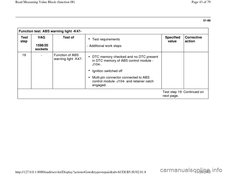
Function test: ABS warning light -K47-
Test
step VAG
1598/20
sockets Test of
Test requirements
- Additional work stepsSpecified
value Corrective
action
19 - Function of ABS
warning light -K47- DTC memory checked and no DTC present
in DTC memory of ABS control module -
J104-. Ignition switched off Multi-pin connector connected to ABS
control module -J104- and retainer catch
engaged.
Test step 19: Continued on
next page.
Pa
ge 43 of 79 Read Measurin
g Value Block
(function 08
)
11/20/2002 htt
p://127.0.0.1:8080/audi/servlet/Dis
play?action=Goto&t
yp
e=re
pair&id=AUDI.B5.SU02.01.8
Page 44 of 79
01-89
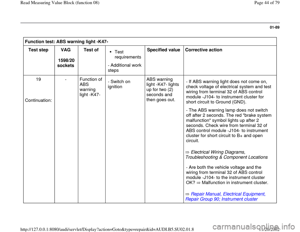
Function test: ABS warning light -K47-
Test step
VAG
1598/20
sockets Test of
Test
requirements
- Additional work
steps Specified value
Corrective action
19
Continuation: - Function of
ABS
warning
light -K47- - Switch on
ignition ABS warning
light -K47- lights
up for two (2)
seconds and
then goes out.
Electrical Wiring Diagrams,
Troubleshooting & Component Locations - If ABS warning light does not come on,
check voltage of electrical system and test
wiring from terminal 32 of ABS control
module -J104- to instrument cluster for
short circuit to Ground (GND).
- The ABS warning lamp does not switch
off after 2 seconds. The red "brake system
malfunction" symbol lights up after 2
seconds. Check wire from terminal 32 of
ABS control module -J104- to instrument
cluster for short circuit to B+ and open
circuit.
Repair Manual, Electrical Equipment,
Repair Group 90; Instrument cluster
- Are both the vehicle voltage and the
wiring from terminal 32 of ABS control
module -J104- to the instrument cluster
OK? Malfunction in instrument cluster. Pa
ge 44 of 79 Read Measurin
g Value Block
(function 08
)
11/20/2002 htt
p://127.0.0.1:8080/audi/servlet/Dis
play?action=Goto&t
yp
e=re
pair&id=AUDI.B5.SU02.01.8
Page 45 of 79
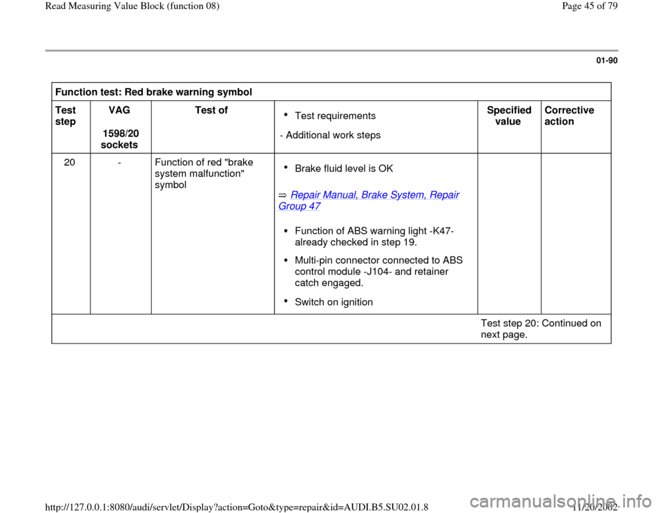
01-90
Function test: Red brake warning symbol
Test
step VAG
1598/20
sockets Test of
Test requirements
- Additional work stepsSpecified
value Corrective
action
20 - Function of red "brake
system malfunction"
symbol
Repair Manual, Brake System, Repair
Group 47
Brake fluid level is OK Function of ABS warning light -K47-
already checked in step 19. Multi-pin connector connected to ABS
control module -J104- and retainer
catch engaged. Switch on ignition
Test step 20: Continued on
next page.
Pa
ge 45 of 79 Read Measurin
g Value Block
(function 08
)
11/20/2002 htt
p://127.0.0.1:8080/audi/servlet/Dis
play?action=Goto&t
yp
e=re
pair&id=AUDI.B5.SU02.01.8
Page 46 of 79
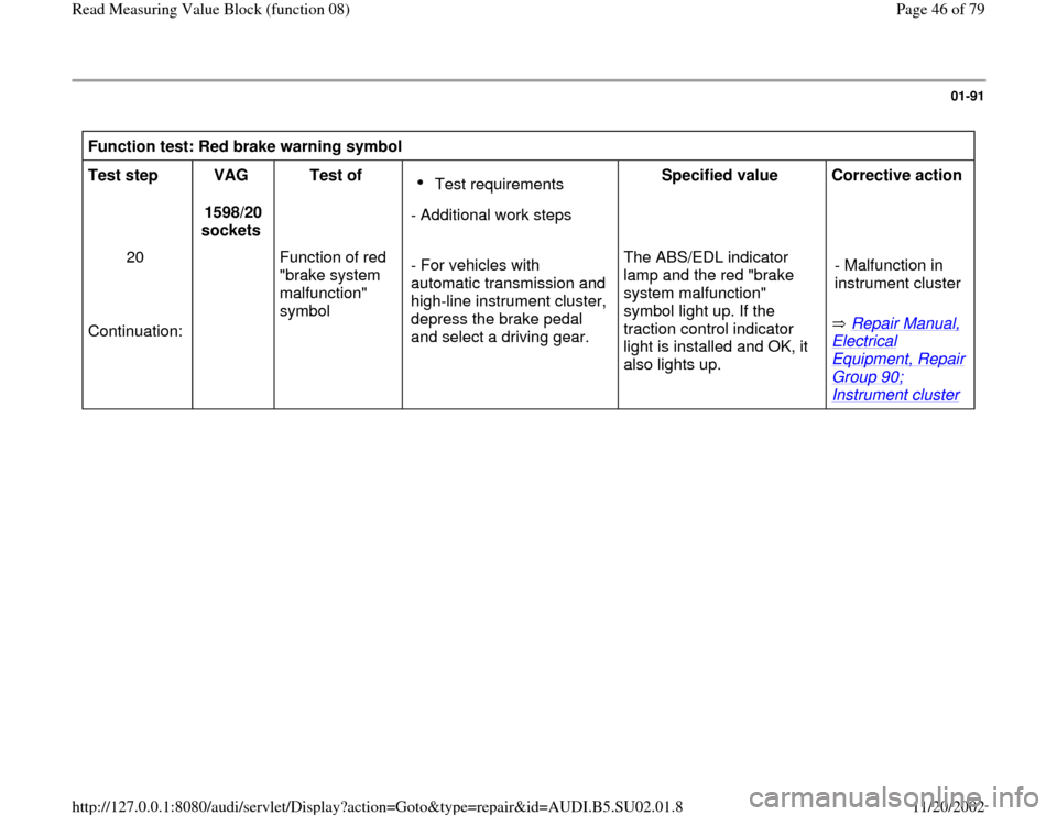
01-91
Function test: Red brake warning symbol
Test step
VAG
1598/20
sockets Test of
Test requirements
- Additional work stepsSpecified value
Corrective action
20
Continuation: Function of red
"brake system
malfunction"
symbol - For vehicles with
automatic transmission and
high-line instrument cluster,
depress the brake pedal
and select a driving gear. The ABS/EDL indicator
lamp and the red "brake
system malfunction"
symbol light up. If the
traction control indicator
light is installed and OK, it
also lights up. Repair Manual,
Electrical Equipment, Repair Group 90; Instrument cluster
- Malfunction in
instrument cluster
Pa
ge 46 of 79 Read Measurin
g Value Block
(function 08
)
11/20/2002 htt
p://127.0.0.1:8080/audi/servlet/Dis
play?action=Goto&t
yp
e=re
pair&id=AUDI.B5.SU02.01.8
Page 53 of 79
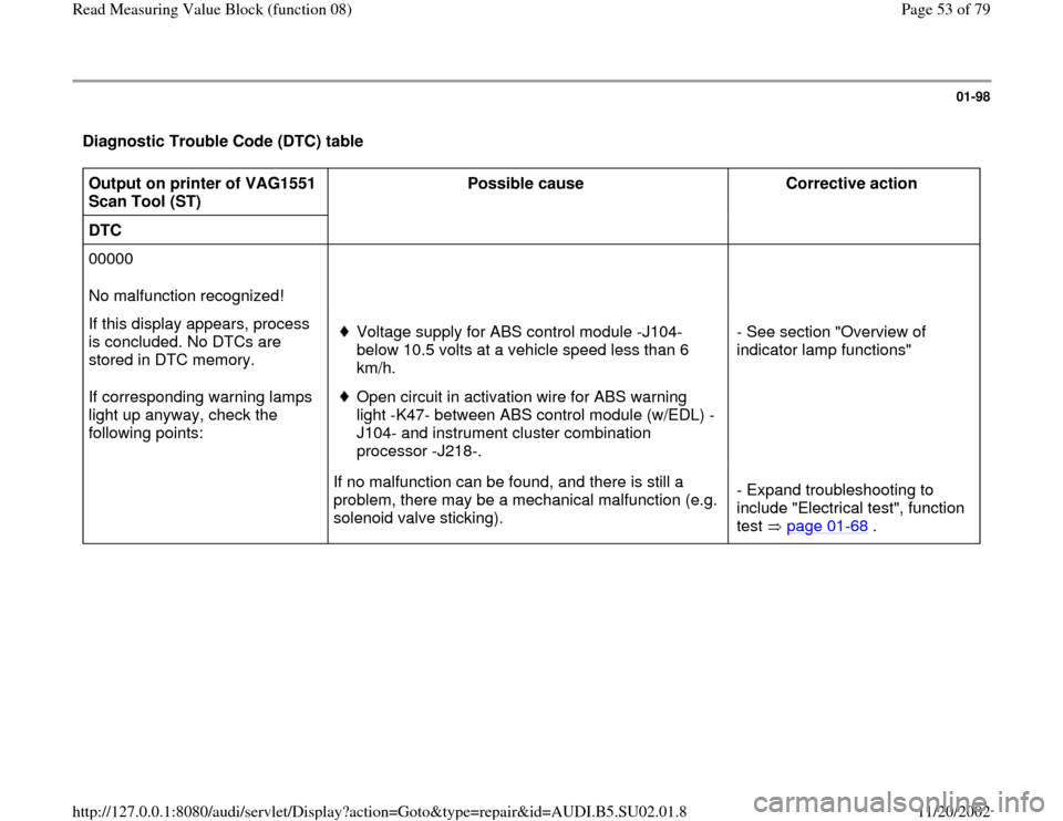
01-98
Diagnostic Trouble Code (DTC) table Output on printer of VAG1551
Scan Tool (ST) Possible cause
Corrective action
DTC
00000
No malfunction recognized!
If this display appears, process
is concluded. No DTCs are
stored in DTC memory.
If corresponding warning lamps
light up anyway, check the
following points:
Voltage supply for ABS control module -J104-
below 10.5 volts at a vehicle speed less than 6
km/h. Open circuit in activation wire for ABS warning
light -K47- between ABS control module (w/EDL) -
J104- and instrument cluster combination
processor -J218-. - See section "Overview of
indicator lamp functions"
If no malfunction can be found, and there is still a
problem, there may be a mechanical malfunction (e.g.
solenoid valve sticking). - Expand troubleshooting to
include "Electrical test", function
test page 01
-68
.
Pa
ge 53 of 79 Read Measurin
g Value Block
(function 08
)
11/20/2002 htt
p://127.0.0.1:8080/audi/servlet/Dis
play?action=Goto&t
yp
e=re
pair&id=AUDI.B5.SU02.01.8
Page 70 of 79
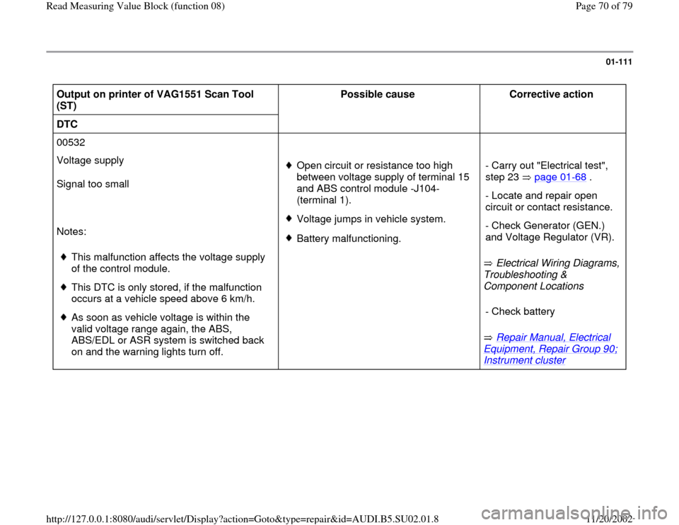
01-111
Output on printer of VAG1551 Scan Tool
(ST) Possible cause
Corrective action
DTC
00532
Voltage supply
Signal too small
Notes:
This malfunction affects the voltage supply
of the control module.
This DTC is only stored, if the malfunction
occurs at a vehicle speed above 6 km/h.
As soon as vehicle voltage is within the
valid voltage range again, the ABS,
ABS/EDL or ASR system is switched back
on and the warning lights turn off.
Open circuit or resistance too high
between voltage supply of terminal 15
and ABS control module -J104-
(terminal 1). Voltage jumps in vehicle system.Battery malfunctioning.
Electrical Wiring Diagrams,
Troubleshooting &
Component Locations
Repair Manual, Electrical
Equipment, Repair Group 90; Instrument cluster
- Carry out "Electrical test",
step 23 page 01-68
.
- Locate and repair open
circuit or contact resistance.
- Check Generator (GEN.)
and Voltage Regulator (VR). - Check battery
Pa
ge 70 of 79 Read Measurin
g Value Block
(function 08
)
11/20/2002 htt
p://127.0.0.1:8080/audi/servlet/Dis
play?action=Goto&t
yp
e=re
pair&id=AUDI.B5.SU02.01.8