engine AUDI A4 1997 B5 / 1.G EVAP User Guide
[x] Cancel search | Manufacturer: AUDI, Model Year: 1997, Model line: A4, Model: AUDI A4 1997 B5 / 1.GPages: 65, PDF Size: 0.77 MB
Page 30 of 65
20-155
If you did not find any malfunction, however the
Leak Detection Pump (LDP) did not function
during the output Diagnostic Test Mode (DTM):
- Replace Leak Detection Pump (LDP) -V144
Page 20
-162
.
If the LED does not blink, although wiring is OK:
- Replace Engine Control Module (ECM):
Repair Manual, Fuel Injection & Ignition,
Repair Group 24
- Generate readiness code:
Repair Manual, Fuel Injection & Ignition,
Repair Group 24
Pa
ge 30 of 65 EVAP s
ystem, servicin
g
11/18/2002 htt
p://127.0.0.1:8080/audi/servlet/Dis
play?action=Goto&t
yp
e=re
pair&id=AUDI.B5.GE04.20.5
Page 32 of 65
20-157
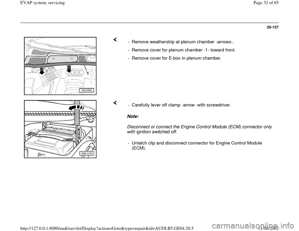
- Remove weatherstrip at plenum chamber -arrows-.
- Remove cover for plenum chamber -1- toward front.
- Remove cover for E-box in plenum chamber.
Note:
Disconnect or connect the Engine Control Module (ECM) connector only
with ignition switched off. - Carefully lever off clamp -arrow- with screwdriver.
- Unlatch clip and disconnect connector for Engine Control Module
(ECM).
Pa
ge 32 of 65 EVAP s
ystem, servicin
g
11/18/2002 htt
p://127.0.0.1:8080/audi/servlet/Dis
play?action=Goto&t
yp
e=re
pair&id=AUDI.B5.GE04.20.5
Page 34 of 65
20-159
If you did not find any malfunction, however the
Leak Detection Pump (LDP) did not function
during the Output Diagnostic Test Mode (DTM):
- Replace LDP Page 20
-162
If the LED does not blink, although wiring is OK:
- Replace the Engine Control Module (ECM)
Repair Manual, Fuel Injection & Ignition,
Repair Group 24
- Generate readiness code:
Repair Manual, Fuel Injection & Ignition,
Repair Group 24
Pa
ge 34 of 65 EVAP s
ystem, servicin
g
11/18/2002 htt
p://127.0.0.1:8080/audi/servlet/Dis
play?action=Goto&t
yp
e=re
pair&id=AUDI.B5.GE04.20.5
Page 51 of 65
20-172
Note:
Fuel system pressurization depends on volume of fuel system and
amount of fuel in tank.
If fuel system pressurization does not stabilize:
CAUTION!
Clamp only soft rubber lines when isolating a leak. To avoid risk of
damage, never clamp hard plastic lines!
Note:
Any flow shown on flow meter indicates a leak. Flow before flow meter
flag set at vehicle leak standard may indicate a sporadic DTC.
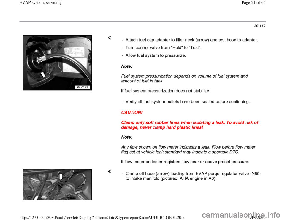
If flow meter on tester registers flow near or above preset pressure: - Attach fuel cap adapter to filler neck (arrow) and test hose to adapter.
- Turn control valve from "Hold" to "Test".
- Allow fuel system to pressurize.
- Verify all fuel system outlets have been sealed before continuing.
- Clamp off hose (arrow) leading from EVAP purge regulator valve -N80-
to intake manifold (pictured: AHA engine in A6).
Pa
ge 51 of 65 EVAP s
ystem, servicin
g
11/18/2002 htt
p://127.0.0.1:8080/audi/servlet/Dis
play?action=Goto&t
yp
e=re
pair&id=AUDI.B5.GE04.20.5
Page 56 of 65
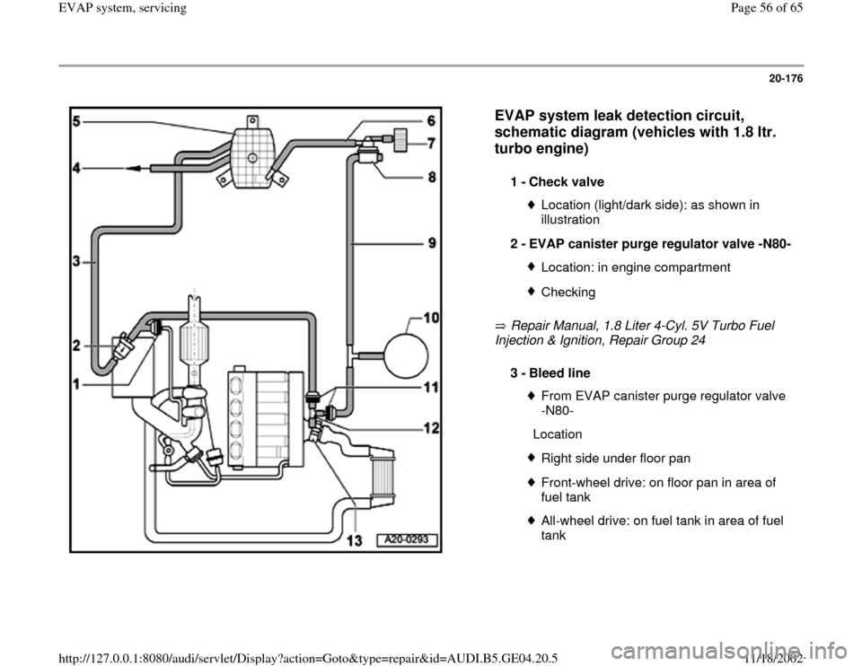
20-176
EVAP system leak detection circuit,
schematic diagram (vehicles with 1.8 ltr.
turbo engine)
Repair Manual, 1.8 Liter 4-Cyl. 5V Turbo Fuel
Injection & Ignition, Repair Group 24 1 -
Check valve
Location (light/dark side): as shown in
illustration
2 -
EVAP canister purge regulator valve -N80-Location: in engine compartmentChecking
3 -
Bleed line
From EVAP canister purge regulator valve
-N80-
LocationRight side under floor panFront-wheel drive: on floor pan in area of
fuel tank All-wheel drive: on fuel tank in area of fuel
tank
Pa
ge 56 of 65 EVAP s
ystem, servicin
g
11/18/2002 htt
p://127.0.0.1:8080/audi/servlet/Dis
play?action=Goto&t
yp
e=re
pair&id=AUDI.B5.GE04.20.5
Page 59 of 65

20-179
T - piece -arrow- is located on left side of engine compartment. Fig. 1 T-piece, location
Pa
ge 59 of 65 EVAP s
ystem, servicin
g
11/18/2002 htt
p://127.0.0.1:8080/audi/servlet/Dis
play?action=Goto&t
yp
e=re
pair&id=AUDI.B5.GE04.20.5
Page 60 of 65
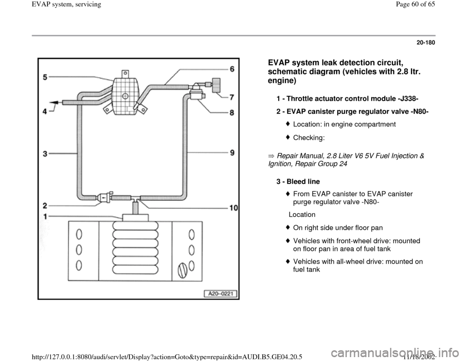
20-180
EVAP system leak detection circuit,
schematic diagram (vehicles with 2.8 ltr.
engine)
Repair Manual, 2.8 Liter V6 5V Fuel Injection &
Ignition, Repair Group 24 1 -
Throttle actuator control module -J338-
2 -
EVAP canister purge regulator valve -N80-Location: in engine compartmentChecking:
3 -
Bleed line
From EVAP canister to EVAP canister
purge regulator valve -N80-
LocationOn right side under floor panVehicles with front-wheel drive: mounted
on floor pan in area of fuel tank Vehicles with all-wheel drive: mounted on
fuel tank
Pa
ge 60 of 65 EVAP s
ystem, servicin
g
11/18/2002 htt
p://127.0.0.1:8080/audi/servlet/Dis
play?action=Goto&t
yp
e=re
pair&id=AUDI.B5.GE04.20.5
Page 62 of 65
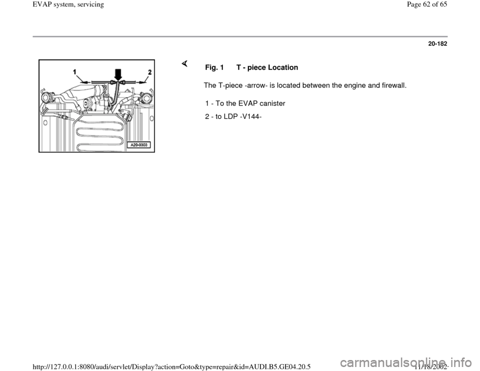
20-182
The T-piece -arrow- is located between the engine and firewall. Fig. 1 T - piece Location
1 - To the EVAP canister
2 - to LDP -V144-
Pa
ge 62 of 65 EVAP s
ystem, servicin
g
11/18/2002 htt
p://127.0.0.1:8080/audi/servlet/Dis
play?action=Goto&t
yp
e=re
pair&id=AUDI.B5.GE04.20.5
Page 63 of 65
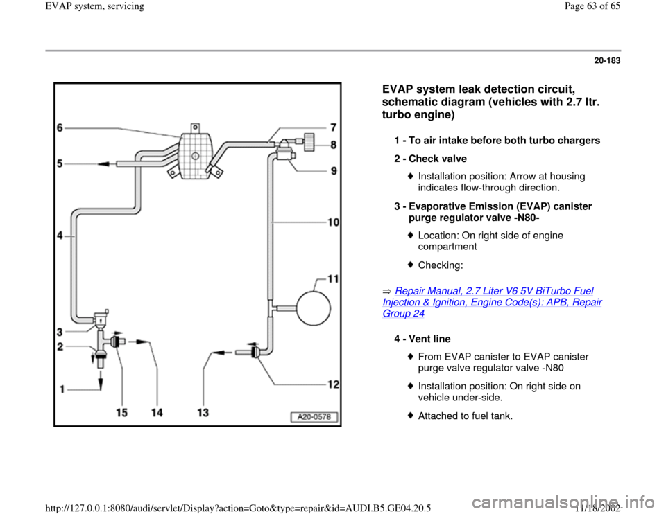
20-183
EVAP system leak detection circuit,
schematic diagram (vehicles with 2.7 ltr.
turbo engine)
Repair Manual, 2.7 Liter V6 5V BiTurbo Fuel
Injection & Ignition, Engine Code(s): APB, Repair Group 24
1 -
To air intake before both turbo chargers
2 -
Check valve Installation position: Arrow at housing
indicates flow-through direction.
3 -
Evaporative Emission (EVAP) canister
purge regulator valve -N80- Location: On right side of engine
compartment Checking:
4 -
Vent line
From EVAP canister to EVAP canister
purge valve regulator valve -N80 Installation position: On right side on
vehicle under-side. Attached to fuel tank.
Pa
ge 63 of 65 EVAP s
ystem, servicin
g
11/18/2002 htt
p://127.0.0.1:8080/audi/servlet/Dis
play?action=Goto&t
yp
e=re
pair&id=AUDI.B5.GE04.20.5