oil AUDI A4 1997 B5 / 1.G Instrument Cluster Location Diagram Through Model Year 1999 Workshop Manual

AUDI A4 1997 B5 / 1.G Instrument Cluster Location Diagram Through Model Year 1999 Workshop Manual A4 1997 B5 / 1.G AUDI AUDI https://www.carmanualsonline.info/img/6/914/w960_914-0.png AUDI A4 1997 B5 / 1.G Instrument Cluster Location Diagram Through Model Year 1999 Workshop Manual

Page 8 of 27
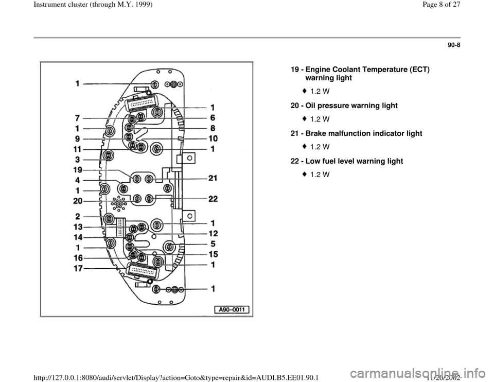
AUDI A4 1997 B5 / 1.G Instrument Cluster Location Diagram Through Model Year 1999 Workshop Manual 90-8
 
  
19 - 
Engine Coolant Temperature (ECT) 
warning light 
1.2 W
20 - 
Oil pressure warning light1.2 W
21 - 
Brake malfunction indicator light1.2 W
22 - 
Low fuel level warning light1.2 W
Pa
ge

Page 10 of 27

AUDI A4 1997 B5 / 1.G Instrument Cluster Location Diagram Through Model Year 1999 Workshop Manual 90-10
 
    
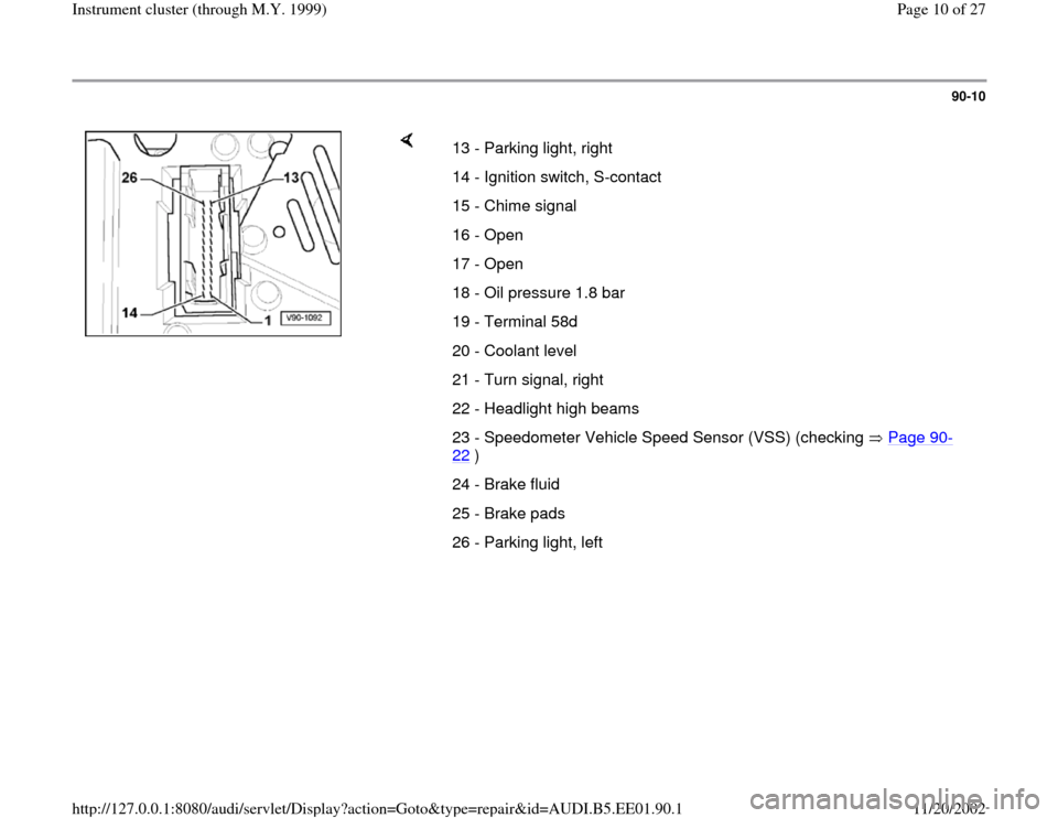
13 - Parking light, right 
14 - Ignition switch, S-contact
15 - Chime signal
16 - Open
17 - Open
18 - Oil pressure 1.8 bar 
19 - Terminal 58d
20 - Coolant level
21 - Turn signal, right
22

Page 15 of 27

AUDI A4 1997 B5 / 1.G Instrument Cluster Location Diagram Through Model Year 1999 Workshop Manual 90-14
 
    
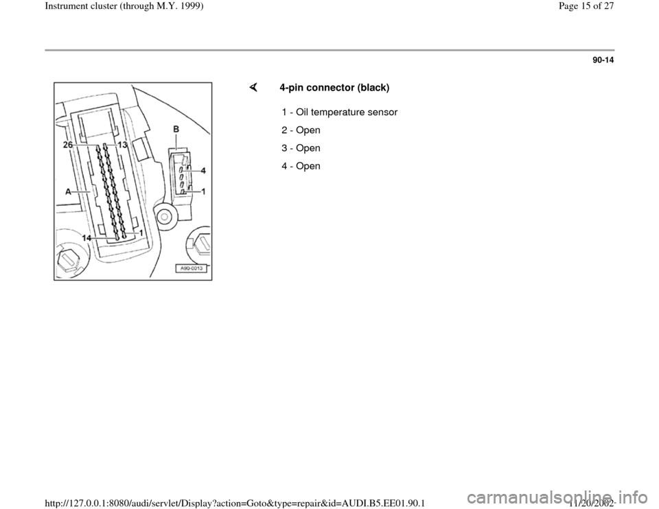
4-pin connector (black)  
1 - Oil temperature sensor 
2 - Open
3 - Open
4 - Open
Pa
ge 15 of 27 Instrument cluster 
(throu
gh M.Y. 1999
)
11/20/2002 htt
p://127.0.0.1:8080/audi/servlet/Di

Page 18 of 27

AUDI A4 1997 B5 / 1.G Instrument Cluster Location Diagram Through Model Year 1999 Workshop Manual 90-17
      
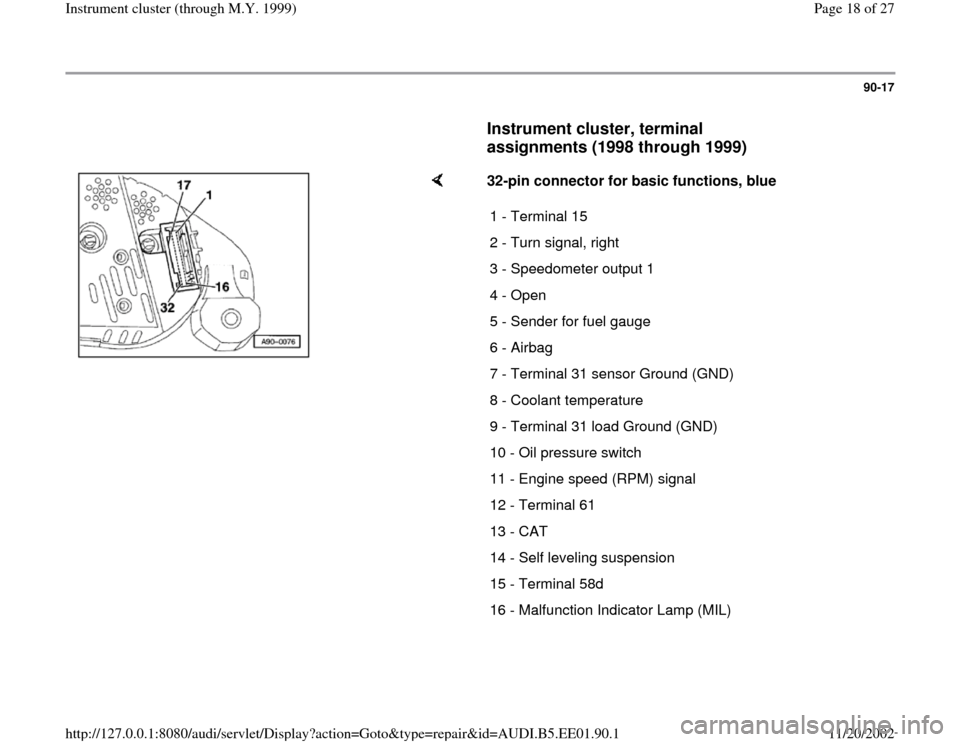
Instrument cluster, terminal 
assignments (1998 through 1999)
 
    
32-pin connector for basic functions, blue  
1 - Terminal 15 
2 - Turn signal, right
3 - Speedometer output 1
4 - Open

Page 21 of 27

AUDI A4 1997 B5 / 1.G Instrument Cluster Location Diagram Through Model Year 1999 Workshop Manual 90-20
 
    
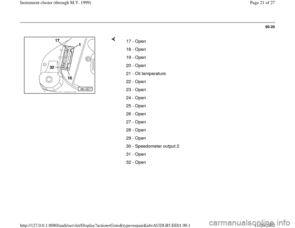
17 - Open
18 - Open
19 - Open
20 - Open
21 - Oil temperature
22 - Open
23 - Open
24 - Open
25 - Open
26 - Open
27 - Open
28 - Open
29 - Open
30 - Speedometer output 2 
31 - Open
32 - Open