trip computer AUDI A4 1997 B5 / 1.G Instrument Cluster Location Diagram Through Model Year 1999 Workshop Manual

AUDI A4 1997 B5 / 1.G Instrument Cluster Location Diagram Through Model Year 1999 Workshop Manual A4 1997 B5 / 1.G AUDI AUDI https://www.carmanualsonline.info/img/6/914/w960_914-0.png AUDI A4 1997 B5 / 1.G Instrument Cluster Location Diagram Through Model Year 1999 Workshop Manual

Page 2 of 27
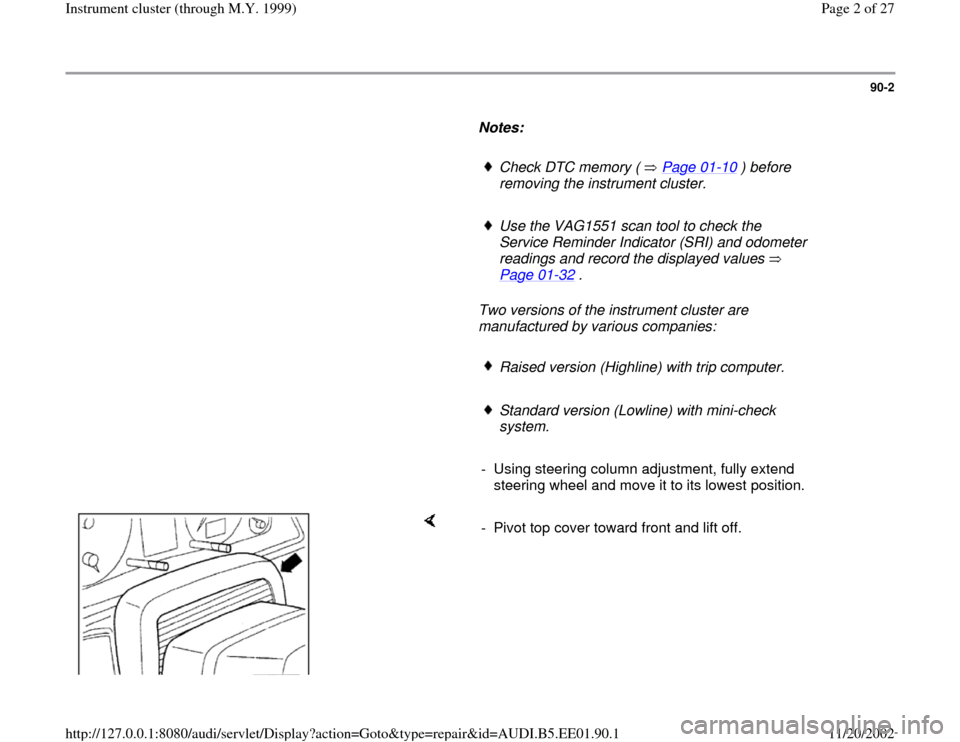
AUDI A4 1997 B5 / 1.G Instrument Cluster Location Diagram Through Model Year 1999 Workshop Manual 90-2
      
Notes:  
     
Check DTC memory (   Page 01
-10
 ) before 
removing the instrument cluster. 
     
Use the VAG1551 scan tool to check the 
Service Reminder Indicator (SRI) and odometer 
re

Page 4 of 27

AUDI A4 1997 B5 / 1.G Instrument Cluster Location Diagram Through Model Year 1999 Workshop Manual 90-4
 
  
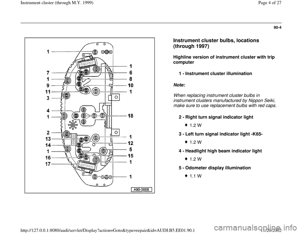
Instrument cluster bulbs, locations 
(through 1997)
 
Highline version of instrument cluster with trip 
computer  
Note:  
When replacing instrument cluster bulbs in 
instrument clusters man

Page 5 of 27

AUDI A4 1997 B5 / 1.G Instrument Cluster Location Diagram Through Model Year 1999 Workshop Manual 90-5
 
  
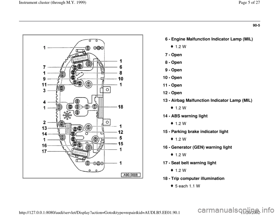
6 - 
Engine Malfunction Indicator Lamp (MIL) 
1.2 W
7 - 
Open 
8 - 
Open 
9 - 
Open 
10 - 
Open 
11 - 
Open 
12 - 
Open 
13 - 
Airbag Malfunction Indicator Lamp (MIL) 1.2 W
14 - 
ABS warning

Page 13 of 27

AUDI A4 1997 B5 / 1.G Instrument Cluster Location Diagram Through Model Year 1999 Workshop Manual 90-13
 
    
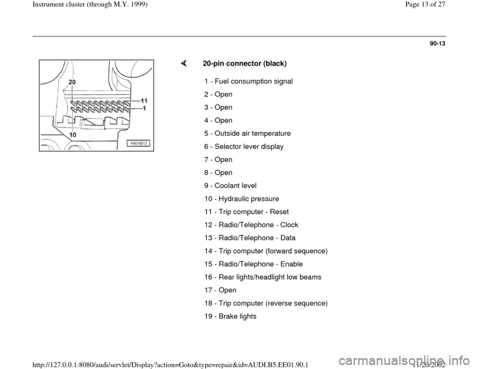
20-pin connector (black)  
1 - Fuel consumption signal 
2 - Open
3 - Open
4 - Open
5 - Outside air temperature 
6 - Selector lever display 
7 - Open
8 - Open
9 - Coolant level
10 - Hydrau

Page 22 of 27

AUDI A4 1997 B5 / 1.G Instrument Cluster Location Diagram Through Model Year 1999 Workshop Manual 90-21
 
    
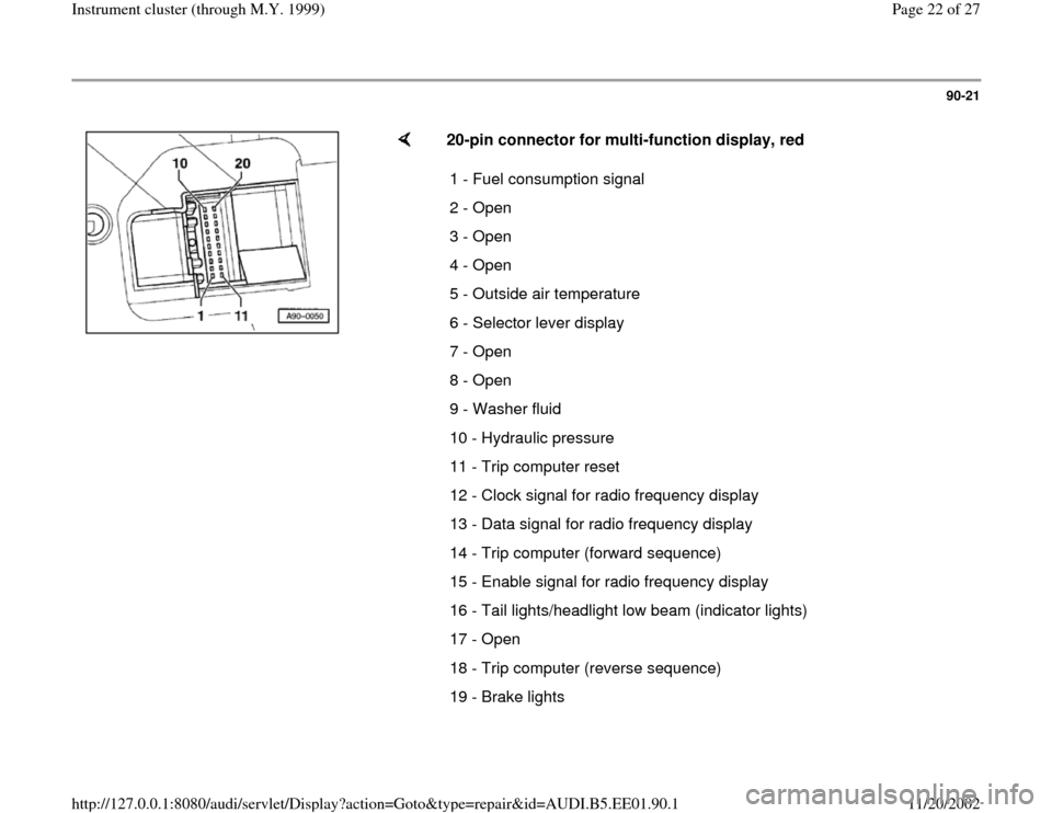
20-pin connector for multi-function display, red  
1 - Fuel consumption signal 
2 - Open
3 - Open
4 - Open
5 - Outside air temperature 
6 - Selector lever display 
7 - Open
8 - Open
9 - W