engine AUDI A4 1997 B5 / 1.G Mechanical Throttle Control Servising
[x] Cancel search | Manufacturer: AUDI, Model Year: 1997, Model line: A4, Model: AUDI A4 1997 B5 / 1.GPages: 18, PDF Size: 0.25 MB
Page 2 of 18
20-187
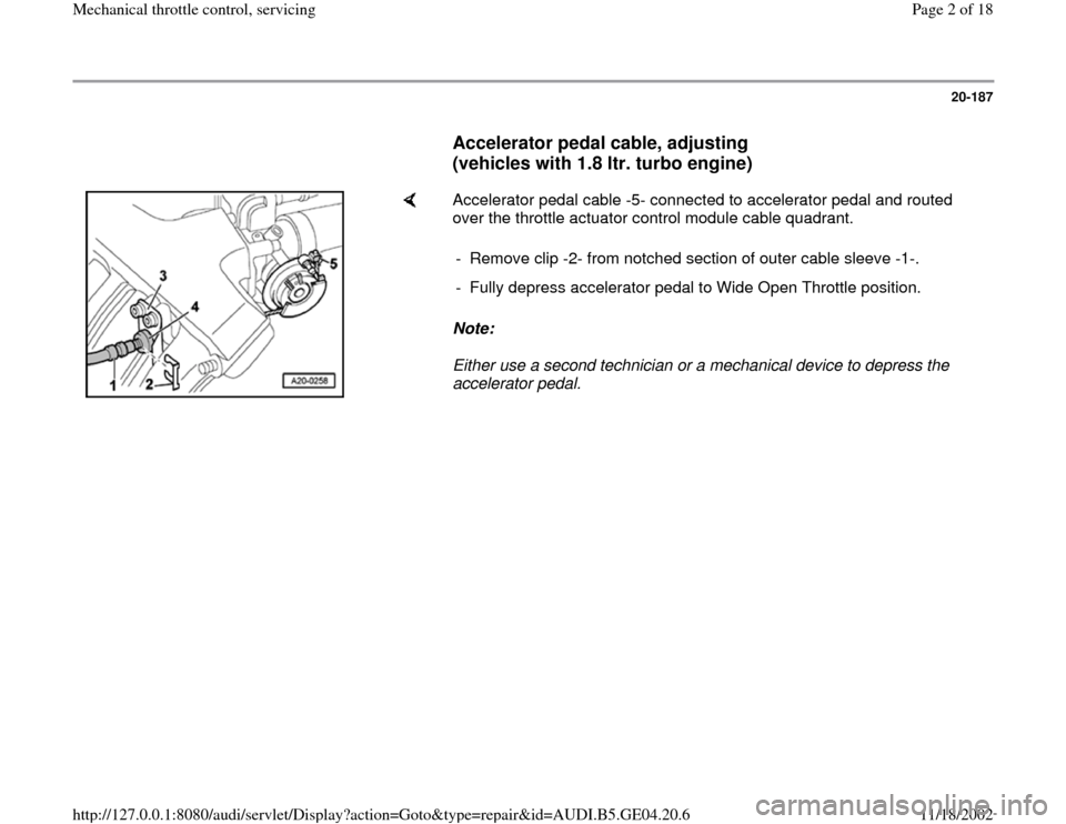
Accelerator pedal cable, adjusting
(vehicles with 1.8 ltr. turbo engine)
Accelerator pedal cable -5- connected to accelerator pedal and routed
over the throttle actuator control module cable quadrant.
Note:
Either use a second technician or a mechanical device to depress the
accelerator pedal. - Remove clip -2- from notched section of outer cable sleeve -1-.
- Fully depress accelerator pedal to Wide Open Throttle position.
Pa
ge 2 of 18 Mechanical throttle control, servicin
g
11/18/2002 htt
p://127.0.0.1:8080/audi/servlet/Dis
play?action=Goto&t
yp
e=re
pair&id=AUDI.B5.GE04.20.6
Page 4 of 18
20-189
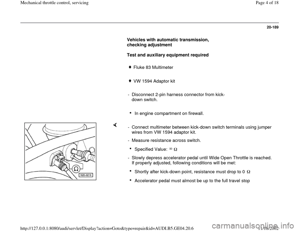
Vehicles with automatic transmission,
checking adjustment
Test and auxiliary equipment required
Fluke 83 Multimeter
VW 1594 Adaptor kit
- Disconnect 2-pin harness connector from kick-
down switch.
In engine compartment on firewall.
- Connect multimeter between kick-down switch terminals using jumper
wires from VW 1594 adaptor kit.
- Measure resistance across switch.
Specified Value:
- Slowly depress accelerator pedal until Wide Open Throttle is reached.
If properly adjusted, following conditions will be met:
Shortly after kick-down point, resistance must drop to 0 Accelerator pedal must almost be up to the full travel stop
Pa
ge 4 of 18 Mechanical throttle control, servicin
g
11/18/2002 htt
p://127.0.0.1:8080/audi/servlet/Dis
play?action=Goto&t
yp
e=re
pair&id=AUDI.B5.GE04.20.6
Page 5 of 18
20-190
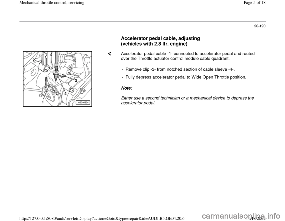
Accelerator pedal cable, adjusting
(vehicles with 2.8 ltr. engine)
Accelerator pedal cable -1- connected to accelerator pedal and routed
over the Throttle actuator control module cable quadrant.
Note:
Either use a second technician or a mechanical device to depress the
accelerator pedal. - Remove clip -3- from notched section of cable sleeve -4-.
- Fully depress accelerator pedal to Wide Open Throttle position.
Pa
ge 5 of 18 Mechanical throttle control, servicin
g
11/18/2002 htt
p://127.0.0.1:8080/audi/servlet/Dis
play?action=Goto&t
yp
e=re
pair&id=AUDI.B5.GE04.20.6
Page 7 of 18
20-192
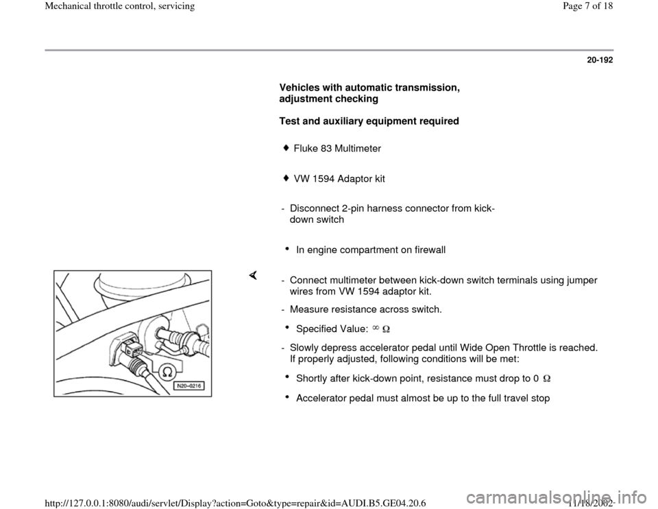
Vehicles with automatic transmission,
adjustment checking
Test and auxiliary equipment required
Fluke 83 Multimeter
VW 1594 Adaptor kit
- Disconnect 2-pin harness connector from kick-
down switch
In engine compartment on firewall
- Connect multimeter between kick-down switch terminals using jumper
wires from VW 1594 adaptor kit.
- Measure resistance across switch.
Specified Value:
- Slowly depress accelerator pedal until Wide Open Throttle is reached.
If properly adjusted, following conditions will be met:
Shortly after kick-down point, resistance must drop to 0 Accelerator pedal must almost be up to the full travel stop
Pa
ge 7 of 18 Mechanical throttle control, servicin
g
11/18/2002 htt
p://127.0.0.1:8080/audi/servlet/Dis
play?action=Goto&t
yp
e=re
pair&id=AUDI.B5.GE04.20.6
Page 8 of 18
20-193
Accelerator pedal cable, removing and
installing (vehicles with 1.8 ltr. turbo
engine)
Removing
- Remove driver's side storage compartment.
Repair Manual, Body Interior, Repair Group
70
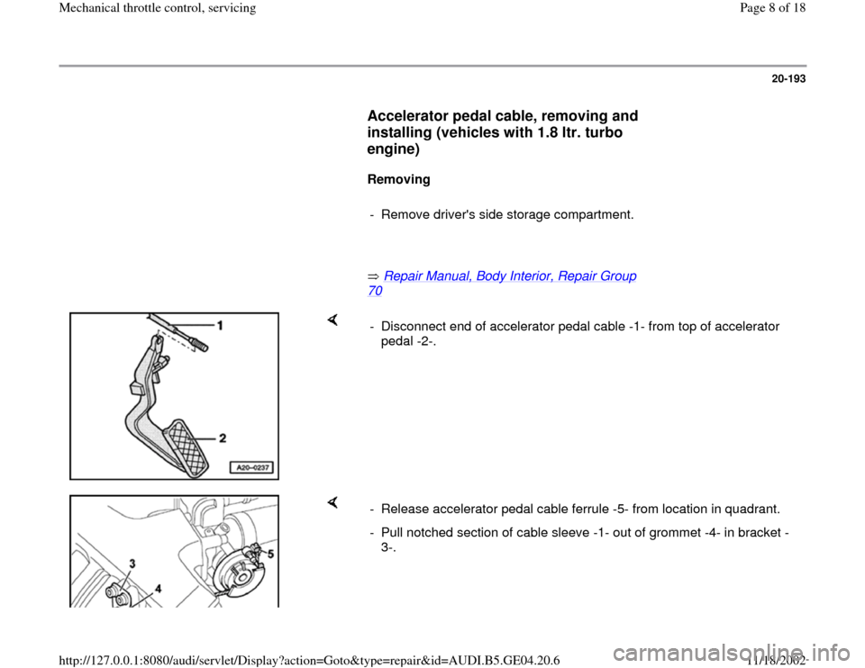
- Disconnect end of accelerator pedal cable -1- from top of accelerator
pedal -2-.
- Release accelerator pedal cable ferrule -5- from location in quadrant.
- Pull notched section of cable sleeve -1- out of grommet -4- in bracket -
3-.
Pa
ge 8 of 18 Mechanical throttle control, servicin
g
11/18/2002 htt
p://127.0.0.1:8080/audi/servlet/Dis
play?action=Goto&t
yp
e=re
pair&id=AUDI.B5.GE04.20.6
Page 10 of 18
20-195
Installing
Installation is performed in the reverse order of
the removal procedure, during installation, note
the following:
- See notes Page 20
-186
.
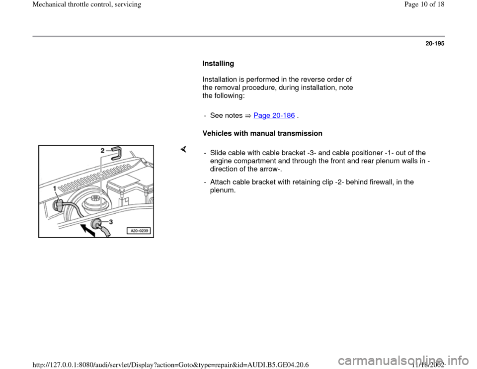
Vehicles with manual transmission
- Slide cable with cable bracket -3- and cable positioner -1- out of the
engine compartment and through the front and rear plenum walls in -
direction of the arrow-.
- Attach cable bracket with retaining clip -2- behind firewall, in the
plenum.
Pa
ge 10 of 18 Mechanical throttle control, servicin
g
11/18/2002 htt
p://127.0.0.1:8080/audi/servlet/Dis
play?action=Goto&t
yp
e=re
pair&id=AUDI.B5.GE04.20.6
Page 11 of 18
20-196
Vehicles with automatic transmission
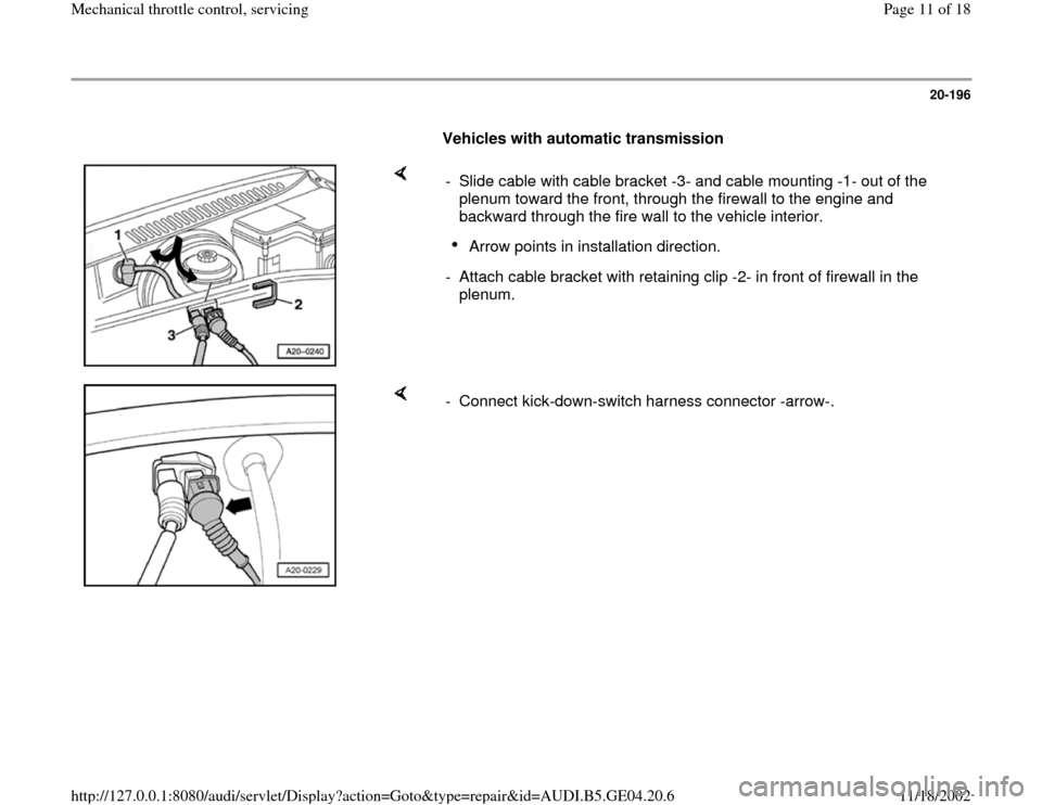
- Slide cable with cable bracket -3- and cable mounting -1- out of the
plenum toward the front, through the firewall to the engine and
backward through the fire wall to the vehicle interior.
Arrow points in installation direction.
- Attach cable bracket with retaining clip -2- in front of firewall in the
plenum.
- Connect kick-down-switch harness connector -arrow-.
Pa
ge 11 of 18 Mechanical throttle control, servicin
g
11/18/2002 htt
p://127.0.0.1:8080/audi/servlet/Dis
play?action=Goto&t
yp
e=re
pair&id=AUDI.B5.GE04.20.6
Page 13 of 18
20-198
Accelerator pedal cable, removing and
installing (vehicles with 2.8 ltr. engine)
Removing
- Remove driver's side storage compartment
Repair Manual, Body Interior, Repair Group
70
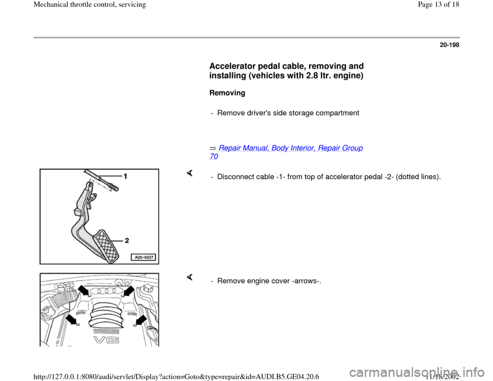
- Disconnect cable -1- from top of accelerator pedal -2- (dotted lines).
- Remove engine cover -arrows-.
Pa
ge 13 of 18 Mechanical throttle control, servicin
g
11/18/2002 htt
p://127.0.0.1:8080/audi/servlet/Dis
play?action=Goto&t
yp
e=re
pair&id=AUDI.B5.GE04.20.6
Page 15 of 18
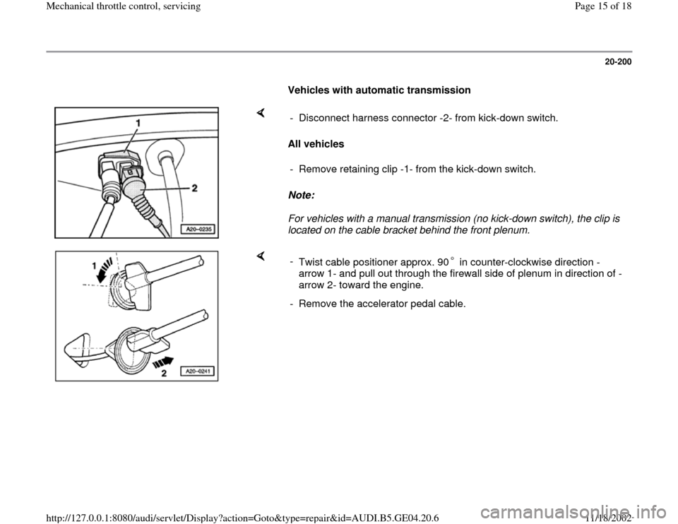
20-200
Vehicles with automatic transmission
All vehicles
Note:
For vehicles with a manual transmission (no kick-down switch), the clip is
located on the cable bracket behind the front plenum. - Disconnect harness connector -2- from kick-down switch.
- Remove retaining clip -1- from the kick-down switch.
-
Twist cable positioner approx. 90 in counter-clockwise direction -
arrow 1- and pull out through the firewall side of plenum in direction of -
arrow 2- toward the engine. - Remove the accelerator pedal cable.
Pa
ge 15 of 18 Mechanical throttle control, servicin
g
11/18/2002 htt
p://127.0.0.1:8080/audi/servlet/Dis
play?action=Goto&t
yp
e=re
pair&id=AUDI.B5.GE04.20.6
Page 17 of 18
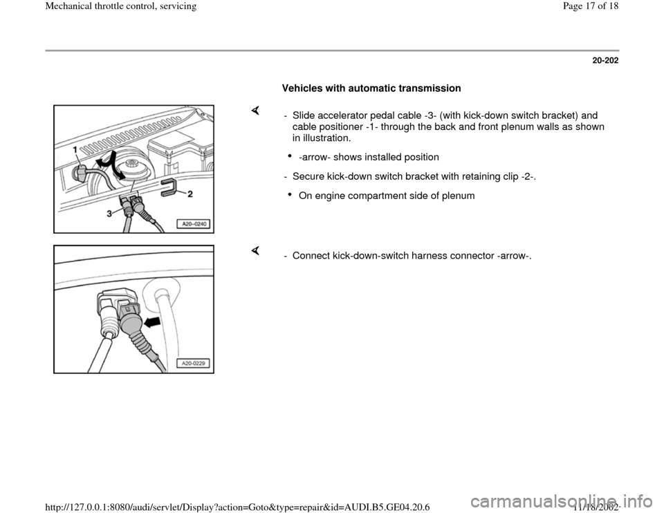
20-202
Vehicles with automatic transmission
- Slide accelerator pedal cable -3- (with kick-down switch bracket) and
cable positioner -1- through the back and front plenum walls as shown
in illustration.
-arrow- shows installed position
- Secure kick-down switch bracket with retaining clip -2-.On engine compartment side of plenum
- Connect kick-down-switch harness connector -arrow-.
Pa
ge 17 of 18 Mechanical throttle control, servicin
g
11/18/2002 htt
p://127.0.0.1:8080/audi/servlet/Dis
play?action=Goto&t
yp
e=re
pair&id=AUDI.B5.GE04.20.6