ECU AUDI A4 1998 B5 / 1.G 01V Transmission Electrical And Electronic Components Workshop Manual
[x] Cancel search | Manufacturer: AUDI, Model Year: 1998, Model line: A4, Model: AUDI A4 1998 B5 / 1.GPages: 23, PDF Size: 0.48 MB
Page 12 of 23

01-22
Installing:
Install in reverse order of removal, with the
following additional steps:
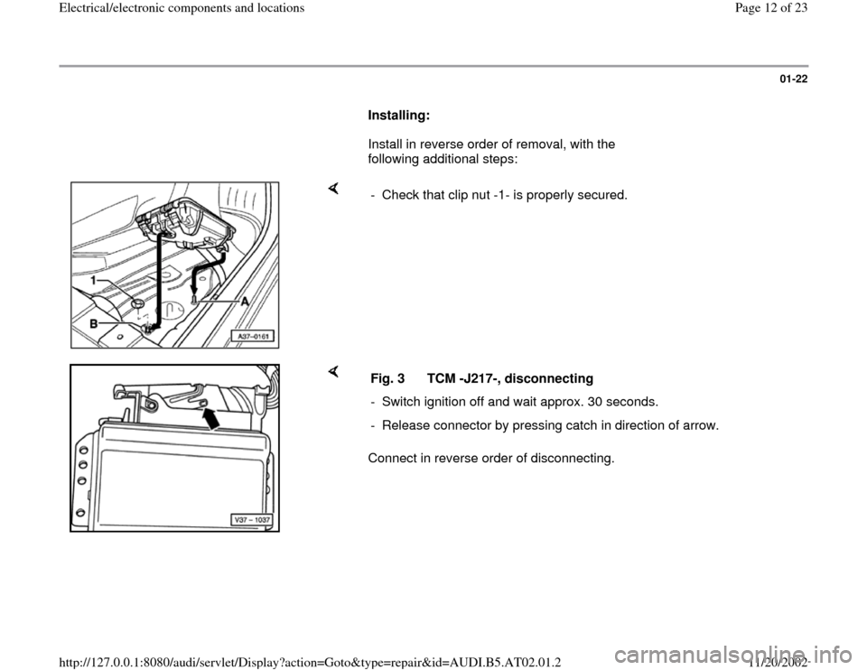
- Check that clip nut -1- is properly secured.
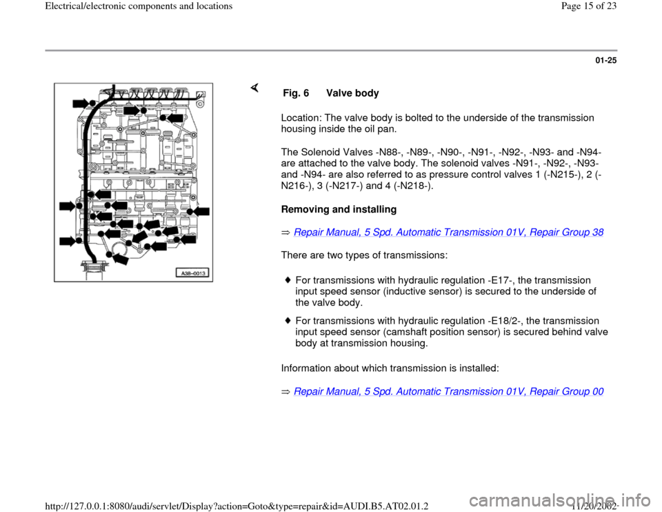
Connect in reverse order of disconnecting. Fig. 3 TCM -J217-, disconnecting
- Switch ignition off and wait approx. 30 seconds.
- Release connector by pressing catch in direction of arrow.
Pa
ge 12 of 23 Electrical/electronic com
ponents and locations
11/20/2002 htt
p://127.0.0.1:8080/audi/servlet/Dis
play?action=Goto&t
yp
e=re
pair&id=AUDI.B5.AT02.01.2
Page 15 of 23

01-25
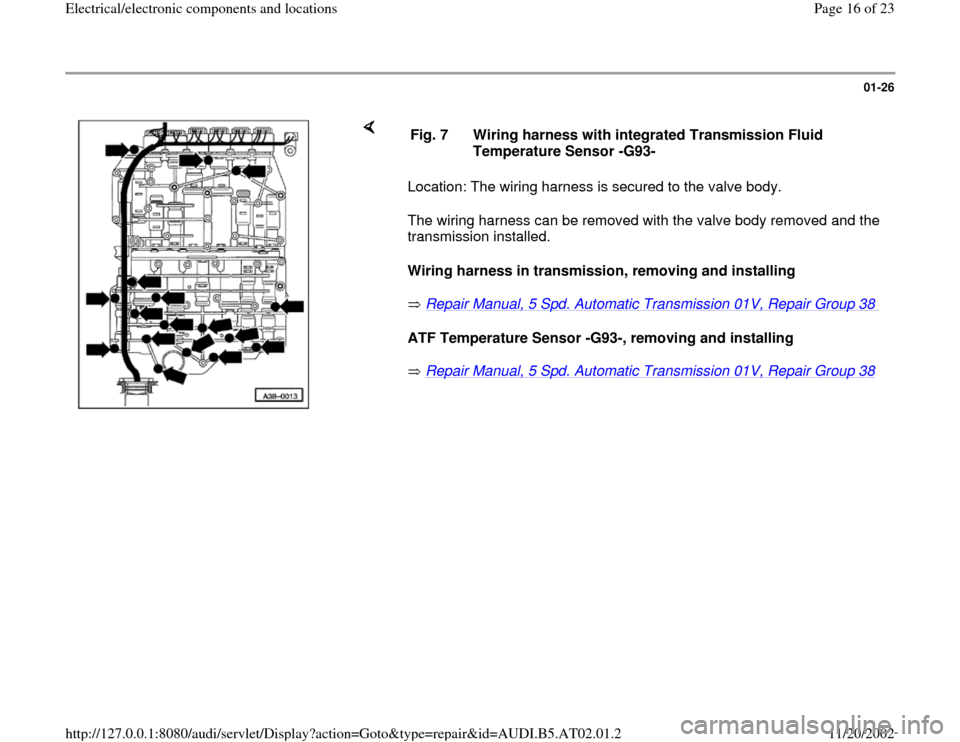
Location: The valve body is bolted to the underside of the transmission
housing inside the oil pan.
The Solenoid Valves -N88-, -N89-, -N90-, -N91-, -N92-, -N93- and -N94-
are attached to the valve body. The solenoid valves -N91-, -N92-, -N93-
and -N94- are also referred to as pressure control valves 1 (-N215-), 2 (-
N216-), 3 (-N217-) and 4 (-N218-).
Removing and installing
Repair Manual, 5 Spd. Automatic Transmission 01V, Repair Group 38
There are two types of transmissions:
Information about which transmission is installed:
Repair Manual, 5 Spd. Automatic Transmission 01V, Repair Group 00 Fig. 6 Valve body
For transmissions with hydraulic regulation -E17-, the transmission
input speed sensor (inductive sensor) is secured to the underside of
the valve body. For transmissions with hydraulic regulation -E18/2-, the transmission
input speed sensor (camshaft position sensor) is secured behind valve
body at transmission housing.
Pa
ge 15 of 23 Electrical/electronic com
ponents and locations
11/20/2002 htt
p://127.0.0.1:8080/audi/servlet/Dis
play?action=Goto&t
yp
e=re
pair&id=AUDI.B5.AT02.01.2
Page 16 of 23

01-26
Location: The wiring harness is secured to the valve body.
The wiring harness can be removed with the valve body removed and the
transmission installed.
Wiring harness in transmission, removing and installing
Repair Manual, 5 Spd. Automatic Transmission 01V, Repair Group 38
ATF Temperature Sensor -G93-, removing and installing
Repair Manual, 5 Spd. Automatic Transmission 01V, Repair Group 38 Fig. 7 Wiring harness with integrated Transmission Fluid
Temperature Sensor -G93-
Pa
ge 16 of 23 Electrical/electronic com
ponents and locations
11/20/2002 htt
p://127.0.0.1:8080/audi/servlet/Dis
play?action=Goto&t
yp
e=re
pair&id=AUDI.B5.AT02.01.2
Page 19 of 23

01-29
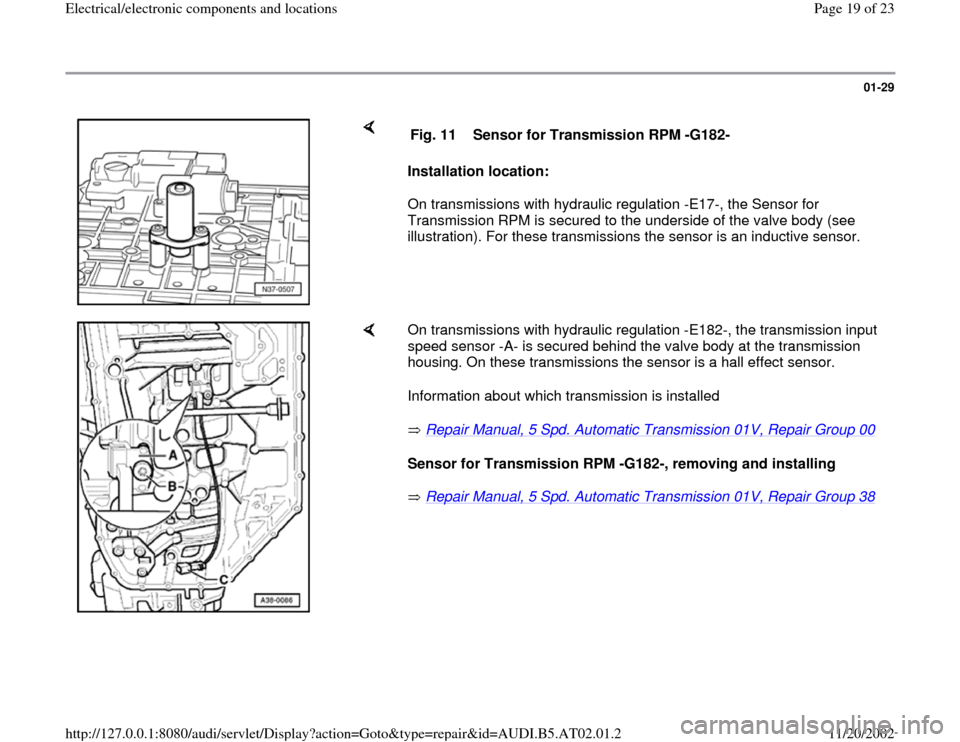
Installation location:
On transmissions with hydraulic regulation -E17-, the Sensor for
Transmission RPM is secured to the underside of the valve body (see
illustration). For these transmissions the sensor is an inductive sensor. Fig. 11 Sensor for Transmission RPM -G182-
On transmissions with hydraulic regulation -E182-, the transmission input
speed sensor -A- is secured behind the valve body at the transmission
housing. On these transmissions the sensor is a hall effect sensor.
Information about which transmission is installed
Repair Manual, 5 Spd. Automatic Transmission 01V, Repair Group 00
Sensor for Transmission RPM -G182-, removing and installing
Repair Manual, 5 Spd. Automatic Transmission 01V, Repair Group 38
Pa
ge 19 of 23 Electrical/electronic com
ponents and locations
11/20/2002 htt
p://127.0.0.1:8080/audi/servlet/Dis
play?action=Goto&t
yp
e=re
pair&id=AUDI.B5.AT02.01.2