wheel AUDI A4 1998 B5 / 1.G 01V Transmission Electrical And Electronic Components Workshop Manual
[x] Cancel search | Manufacturer: AUDI, Model Year: 1998, Model line: A4, Model: AUDI A4 1998 B5 / 1.GPages: 23, PDF Size: 0.48 MB
Page 14 of 23

01-24
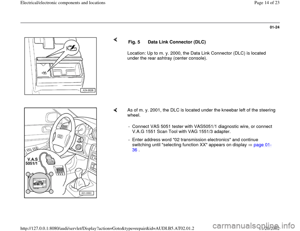
Location: Up to m. y. 2000, the Data Link Connector (DLC) is located
under the rear ashtray (center console).
Fig. 5 Data Link Connector (DLC)
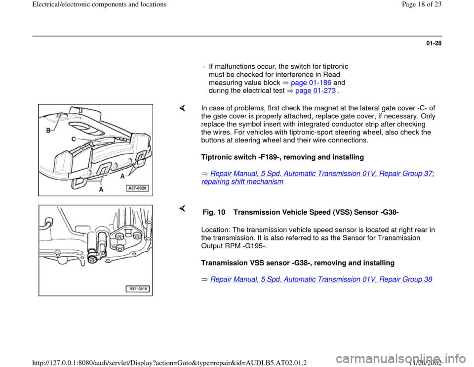
As of m. y. 2001, the DLC is located under the kneebar left of the steering
wheel.
- Connect VAS 5051 tester with VAS5051/1 diagnostic wire, or connect
V.A.G 1551 Scan Tool with VAG 1551/3 adapter.
- Enter address word "02 transmission electronics" and continue
switching until "selecting function XX" appears on display page 01
-
36
.
Pa
ge 14 of 23 Electrical/electronic com
ponents and locations
11/20/2002 htt
p://127.0.0.1:8080/audi/servlet/Dis
play?action=Goto&t
yp
e=re
pair&id=AUDI.B5.AT02.01.2
Page 18 of 23

01-28
- If malfunctions occur, the switch for tiptronic
must be checked for interference in Read
measuring value block page 01
-186
and
during the electrical test page 01
-273
.
In case of problems, first check the magnet at the lateral gate cover -C- of
the gate cover is properly attached, replace gate cover, if necessary. Only
replace the symbol insert with integrated conductor strip after checking
the wires. For vehicles with tiptronic-sport steering wheel, also check the
buttons at steering wheel and their wire connections.
Tiptronic switch -F189-, removing and installing
Repair Manual, 5 Spd. Automatic Transmission 01V, Repair Group 37; repairing shift mechanism
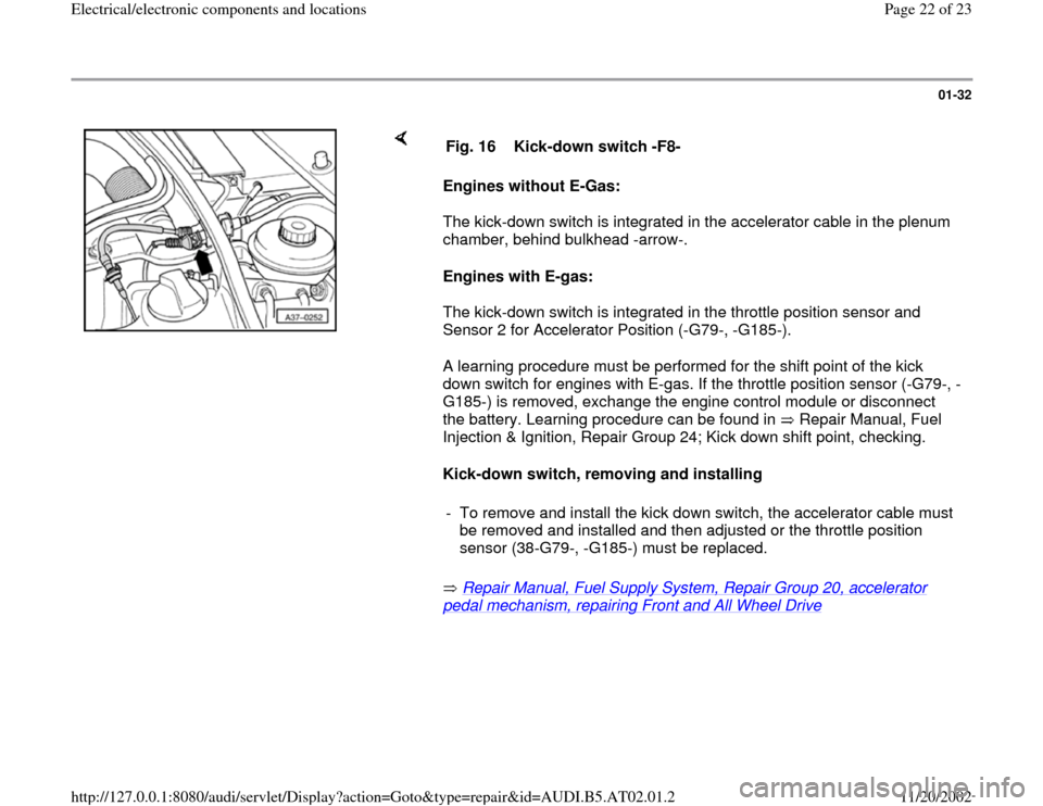
Location: The transmission vehicle speed sensor is located at right rear in
the transmission. It is also referred to as the Sensor for Transmission
Output RPM -G195-.
Transmission VSS sensor -G38-, removing and installing
Repair Manual, 5 Spd. Automatic Transmission 01V, Repair Group 38
Fig. 10 Transmission Vehicle Speed (VSS) Sensor -G38-
Pa
ge 18 of 23 Electrical/electronic com
ponents and locations
11/20/2002 htt
p://127.0.0.1:8080/audi/servlet/Dis
play?action=Goto&t
yp
e=re
pair&id=AUDI.B5.AT02.01.2
Page 22 of 23

01-32
Engines without E-Gas:
The kick-down switch is integrated in the accelerator cable in the plenum
chamber, behind bulkhead -arrow-.
Engines with E-gas:
The kick-down switch is integrated in the throttle position sensor and
Sensor 2 for Accelerator Position (-G79-, -G185-).
A learning procedure must be performed for the shift point of the kick
down switch for engines with E-gas. If the throttle position sensor (-G79-, -
G185-) is removed, exchange the engine control module or disconnect
the battery. Learning procedure can be found in Repair Manual, Fuel
Injection & Ignition, Repair Group 24; Kick down shift point, checking.
Kick-down switch, removing and installing
Repair Manual, Fuel Supply System, Repair Group 20, accelerator pedal mechanism, repairing Front and All Wheel Drive
Fig. 16 Kick-down switch -F8-
- To remove and install the kick down switch, the accelerator cable must
be removed and installed and then adjusted or the throttle position
sensor (38-G79-, -G185-) must be replaced.
Pa
ge 22 of 23 Electrical/electronic com
ponents and locations
11/20/2002 htt
p://127.0.0.1:8080/audi/servlet/Dis
play?action=Goto&t
yp
e=re
pair&id=AUDI.B5.AT02.01.2