battery AUDI A4 1998 B5 / 1.G AC System Electrical Testing Workshop Manual
[x] Cancel search | Manufacturer: AUDI, Model Year: 1998, Model line: A4, Model: AUDI A4 1998 B5 / 1.GPages: 47, PDF Size: 0.16 MB
Page 1 of 47
01-115
A/C system, electrical testing
Notes:
Vehicles 1997 page 01
-135
.
VAG1598 test box must not be connected to -
E87- when performing On Board Diagnostic
with VAG1551 Scan Tool (ST)
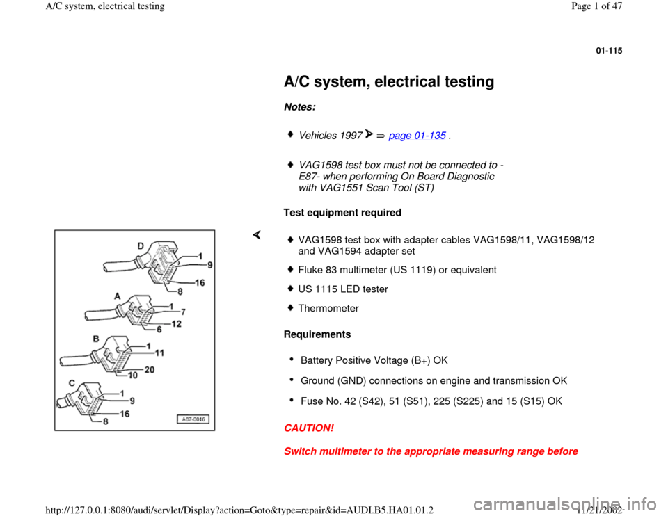
Test equipment required
Requirements
CAUTION!
Switch multimeter to the appropriate measuring range before
VAG1598 test box with adapter cables VAG1598/11, VAG1598/12
and VAG1594 adapter set Fluke 83 multimeter (US 1119) or equivalentUS 1115 LED tester ThermometerBattery Positive Voltage (B+) OK Ground (GND) connections on engine and transmission OK Fuse No. 42 (S42), 51 (S51), 225 (S225) and 15 (S15) OK
Pa
ge 1 of 47 A/C s
ystem, electrical testin
g
11/21/2002 htt
p://127.0.0.1:8080/audi/servlet/Dis
play?action=Goto&t
yp
e=re
pair&id=AUDI.B5.HA01.01.2
Page 8 of 47
01-120
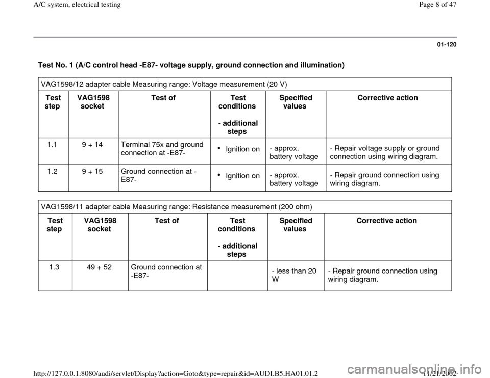
Test No. 1 (A/C control head -E87- voltage supply, ground connection and illumination) VAG1598/12 adapter cable Measuring range: Voltage measurement (20 V)
Test
step VAG1598
socket Test of
Test
conditions
- additional
steps Specified
values Corrective action
1.1 9 + 14 Terminal 75x and ground
connection at -E87-
Ignition on - approx.
battery voltage - Repair voltage supply or ground
connection using wiring diagram.
1.2 9 + 15 Ground connection at -
E87- Ignition on - approx.
battery voltage - Repair ground connection using
wiring diagram.
VAG1598/11 adapter cable Measuring range: Resistance measurement (200 ohm)
Test
step VAG1598
socket Test of
Test
conditions
- additional
steps Specified
values Corrective action
1.3 49 + 52 Ground connection at
-E87-
- less than 20
W - Repair ground connection using
wiring diagram.
Pa
ge 8 of 47 A/C s
ystem, electrical testin
g
11/21/2002 htt
p://127.0.0.1:8080/audi/servlet/Dis
play?action=Goto&t
yp
e=re
pair&id=AUDI.B5.HA01.01.2
Page 9 of 47
01-121
VAG1598/12 adapter cable Measuring range: Voltage measurement (20 V)
Test
step VAG1598
socket Test of
Test
conditions
- additional
steps Specified values
Corrective action
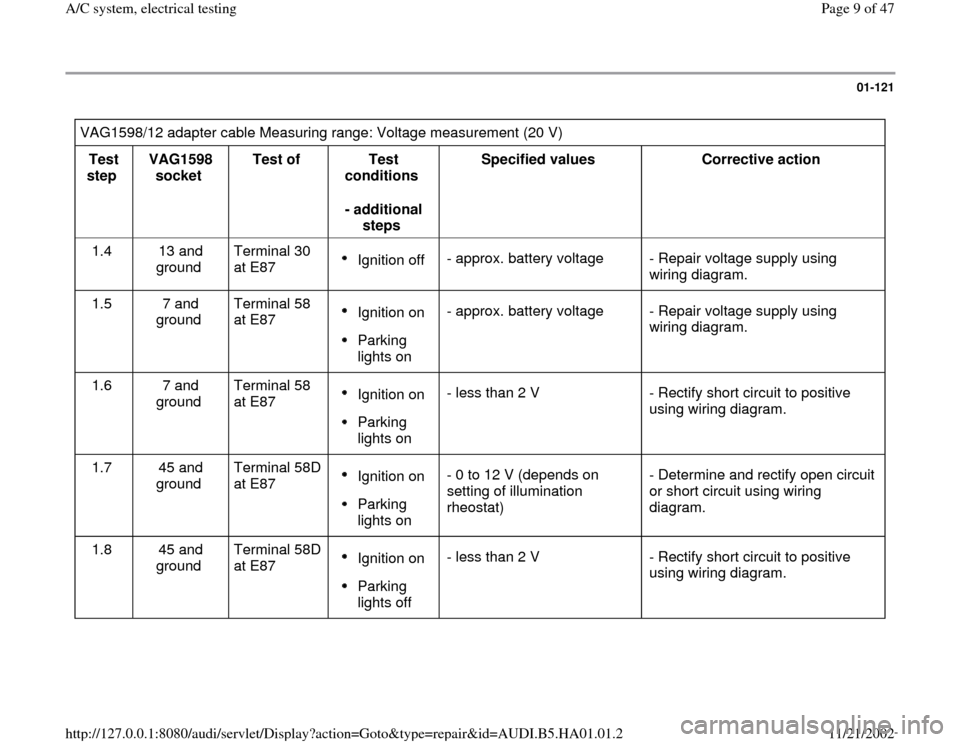
1.4 13 and
ground Terminal 30
at E87
Ignition off - approx. battery voltage - Repair voltage supply using
wiring diagram.
1.5 7 and
ground Terminal 58
at E87 Ignition on Parking
lights on - approx. battery voltage - Repair voltage supply using
wiring diagram.
1.6 7 and
ground Terminal 58
at E87 Ignition on Parking
lights on - less than 2 V - Rectify short circuit to positive
using wiring diagram.
1.7 45 and
ground Terminal 58D
at E87 Ignition on Parking
lights on - 0 to 12 V (depends on
setting of illumination
rheostat) - Determine and rectify open circuit
or short circuit using wiring
diagram.
1.8 45 and
ground Terminal 58D
at E87 Ignition on Parking
lights off - less than 2 V - Rectify short circuit to positive
using wiring diagram.
Pa
ge 9 of 47 A/C s
ystem, electrical testin
g
11/21/2002 htt
p://127.0.0.1:8080/audi/servlet/Dis
play?action=Goto&t
yp
e=re
pair&id=AUDI.B5.HA01.01.2
Page 13 of 47
01-124
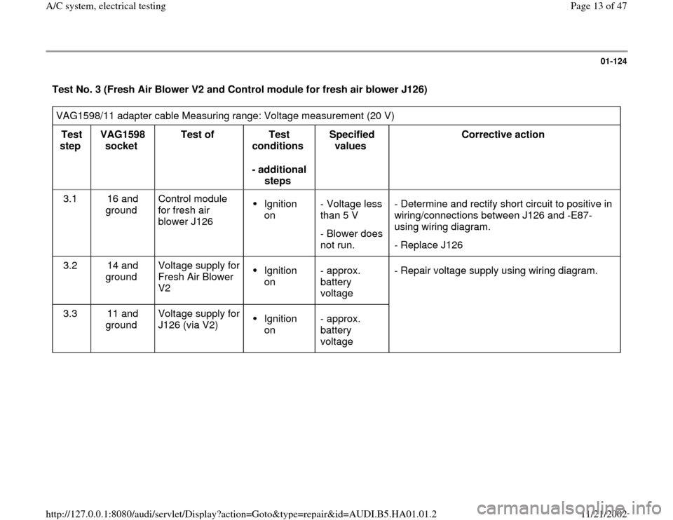
Test No. 3 (Fresh Air Blower V2 and Control module for fresh air blower J126) VAG1598/11 adapter cable Measuring range: Voltage measurement (20 V)
Test
step VAG1598
socket Test of
Test
conditions
- additional
steps Specified
values Corrective action
3.1 16 and
ground Control module
for fresh air
blower J126
Ignition
on - Voltage less
than 5 V
- Blower does
not run. - Determine and rectify short circuit to positive in
wiring/connections between J126 and -E87-
using wiring diagram.
- Replace J126
3.2 14 and
ground Voltage supply for
Fresh Air Blower
V2 Ignition
on - approx.
battery
voltage - Repair voltage supply using wiring diagram.
3.3 11 and
ground Voltage supply for
J126 (via V2) Ignition
on - approx.
battery
voltage
Pa
ge 13 of 47 A/C s
ystem, electrical testin
g
11/21/2002 htt
p://127.0.0.1:8080/audi/servlet/Dis
play?action=Goto&t
yp
e=re
pair&id=AUDI.B5.HA01.01.2
Page 21 of 47
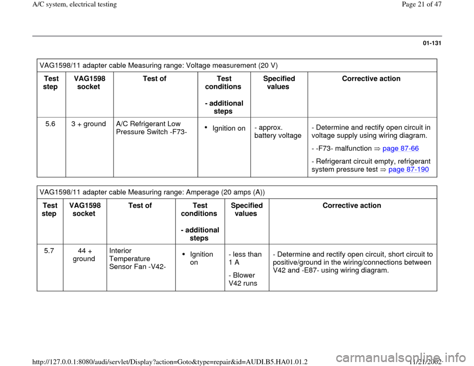
01-131
VAG1598/11 adapter cable Measuring range: Voltage measurement (20 V)
Test
step VAG1598
socket Test of
Test
conditions
- additional
steps Specified
values Corrective action
5.6 3 + ground A/C Refrigerant Low
Pressure Switch -F73-
Ignition on- approx.
battery voltage - Determine and rectify open circuit in
voltage supply using wiring diagram.
- -F73- malfunction page 87
-66
- Refrigerant circuit empty, refrigerant
system pressure test page 87
-190
VAG1598/11 adapter cable Measuring range: Amperage (20 amps (A))
Test
step VAG1598
socket Test of
Test
conditions
- additional
steps Specified
values Corrective action
5.7 44 +
ground Interior
Temperature
Sensor Fan -V42-
Ignition
on - less than
1 A
- Blower
V42 runs - Determine and rectify open circuit, short circuit to
positive/ground in the wiring/connections between
V42 and -E87- using wiring diagram.
Pa
ge 21 of 47 A/C s
ystem, electrical testin
g
11/21/2002 htt
p://127.0.0.1:8080/audi/servlet/Dis
play?action=Goto&t
yp
e=re
pair&id=AUDI.B5.HA01.01.2
Page 27 of 47

01-136
Test No. 1 (A/C control head -E87- voltage supply, ground connection) Adapter cable VAG1598/12
Measuring range: Voltage measurement (20 V)
Test
Step VAG1598
socket Test of
Test
conditions
- additional
steps Specified value
Corrective action
1.1 9 + 14 Terminal 15 and ground
connection at -E87-
Ignition on - approx.
battery voltage. - Repair voltage supply or ground
connection using wiring diagram.
1.2 9 + 15 terminal 15 and ground
connection at -E87- Ignition on - approx.
battery voltage. - Repair ground connection using
wiring diagram.
1.3 page 01
-120
1.4 Not for 1997. Terminal 30 no longer connected
1.5 to
1.8 These test steps are conducted only for vehicles up to and including m.y. 1997 (A/C control head with Part. No.
8D0 820 043 and Part No. 8L0 820 043 up to Part No. index letter "C").
Pa
ge 27 of 47 A/C s
ystem, electrical testin
g
11/21/2002 htt
p://127.0.0.1:8080/audi/servlet/Dis
play?action=Goto&t
yp
e=re
pair&id=AUDI.B5.HA01.01.2
Page 39 of 47

01-147
Notes:
The following test steps are only performed for A/C control heads -E87- with two displays:
Teststep 2.2 (the instrument panel interior temperature sensor -G56- is installed in A/C control heads -E87- with one
display)
Test step 5.7 (the interior temperature sensor fan -V42- is installed in A/C control heads -E87- with one display)
Switch on test area at VAG1526 multimeter: voltage test (20 V =)
VAG1598/11 adapter cable connected
Test
step VAG1598A
socket Test of
Test
requirements
- additional
operations Specified
value Corrective action
1.15
4) 46 + Ground
3) Power supply
terminal 58 of A/C
control head -E87-
Ignition
switched on Park light
switched on
approx.
battery
voltage - Locate and repair open circuit or short
circuit to Ground in wiring connection to
A/C control head -E87- using wiring
diagram
1.16
4) 46 + Ground
3) Power supply
terminal 58 of A/C
control head -E87-
Ignition
switched on Park light
- Locate and repair open circuit or short
circuit to Ground in wiring connection to
A/C control head -E87- using wiring
diagram.
Pa
ge 39 of 47 A/C s
ystem, electrical testin
g
11/21/2002 htt
p://127.0.0.1:8080/audi/servlet/Dis
play?action=Goto&t
yp
e=re
pair&id=AUDI.B5.HA01.01.2
Page 41 of 47

01-148
Switch on test area at VAG1526 multimeter: voltage test (20 V)
VAG1598/12 adapter cable connected
Test
step VAG1598A
socket Test of
Test
requirements
- additional
operations Specified
value Corrective action
1.17
4) 8
+
14
Terminal 15 and Ground
connection at A/C control head
-E87- (power supply for A/C
clutch)
Ignition
switched on
approx.
battery
voltage - Repair power supply or
Ground connection
according to wiring
diagram
4) Only perform this test step for an A/C control head with one display.
Pa
ge 41 of 47 A/C s
ystem, electrical testin
g
11/21/2002 htt
p://127.0.0.1:8080/audi/servlet/Dis
play?action=Goto&t
yp
e=re
pair&id=AUDI.B5.HA01.01.2