fuel AUDI A4 1998 B5 / 1.G AC System On Board Diagnostic Workshop Manual
[x] Cancel search | Manufacturer: AUDI, Model Year: 1998, Model line: A4, Model: AUDI A4 1998 B5 / 1.GPages: 91, PDF Size: 0.32 MB
Page 31 of 91

01-24
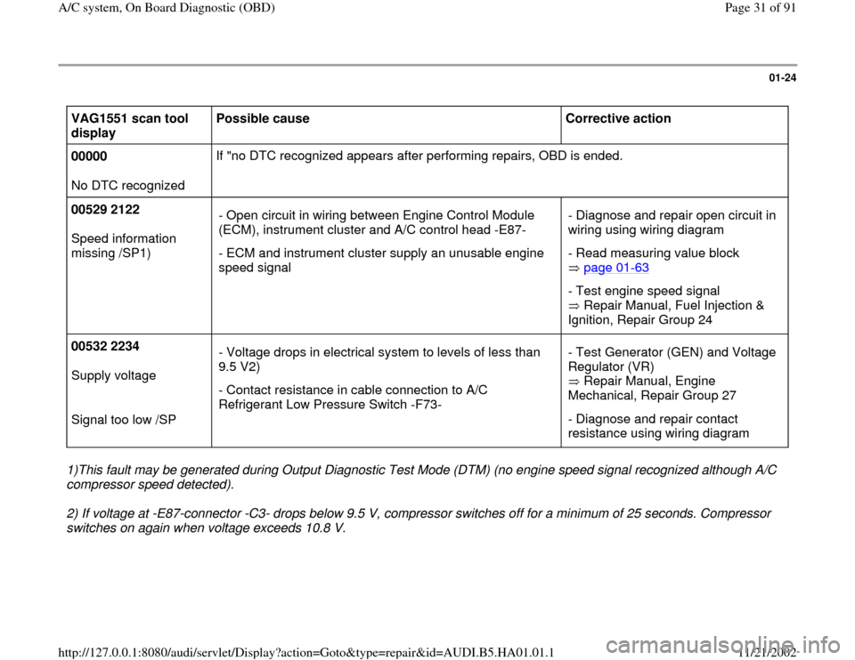
VAG1551 scan tool
display Possible cause
Corrective action
00000
No DTC recognized If "no DTC recognized appears after performing repairs, OBD is ended.
00529 2122
Speed information
missing /SP1) - Open circuit in wiring between Engine Control Module
(ECM), instrument cluster and A/C control head -E87-
- ECM and instrument cluster supply an unusable engine
speed signal - Diagnose and repair open circuit in
wiring using wiring diagram
- Read measuring value block
page 01
-63
- Test engine speed signal
Repair Manual, Fuel Injection &
Ignition, Repair Group 24
00532 2234
Supply voltage
Signal too low /SP - Voltage drops in electrical system to levels of less than
9.5 V2)
- Contact resistance in cable connection to A/C
Refrigerant Low Pressure Switch -F73- - Test Generator (GEN) and Voltage
Regulator (VR)
Repair Manual, Engine
Mechanical, Repair Group 27
- Diagnose and repair contact
resistance using wiring diagram
1)This fault may be generated during Output Diagnostic Test Mode (DTM) (no engine speed signal recognized although A/C
compressor speed detected).
2) If voltage at -E87-connector -C3- drops below 9.5 V, compressor switches off for a minimum of 25 seconds. Compressor
switches on again when voltage exceeds 10.8 V.
Pa
ge 31 of 91 A/C s
ystem, On Board Dia
gnostic
(OBD
)
11/21/2002 htt
p://127.0.0.1:8080/audi/servlet/Dis
play?action=Goto&t
yp
e=re
pair&id=AUDI.B5.HA01.01.1
Page 65 of 91

01-46
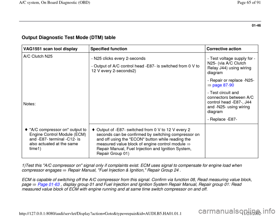
Output Diagnostic Test Mode (DTM) table
VAG1551 scan tool display
Specified function
Corrective action
A/C Clutch N25
Notes: - N25 clicks every 2-seconds
- Output of A/C control head -E87- is switched from 0 V to
12 V every 2-seconds2) - Test voltage supply for -
N25- (via A/C Clutch
Relay J44) using wiring
diagram
- Repair or replace -N25-
page 87
-90
- Test circuit and
connectors between A/C
control head -E87-, J44
and -N25- using wiring
diagram
- Replace -E87-
"A/C compressor on" output to
Engine Control Module (ECM)
and -E87- terminal -C12- is
also actuated at the same
time1)
Output of -E87- switched from 0 V to 12 V every 2
seconds can be confirmed by switching compressor on
and off using the "ECON" button while reading the
measured value block of engine control module
Repair Manual, Fuel Injection and Ignition System,
Repair Group 01)
1)Test this "A/C compressor on" signal only if complaints exist. ECM uses signal to compensate for engine load when
compressor engages Repair Manual, "Fuel Injection & Ignition," Repair Group 24 . ECM is capable of switching off the A/C compressor from this signal. Confirm via function 08, Read measuring value block,
page Page 01
-63
, display group 01 and Fuel Injection and Ignition System Repair Manual, Repair group 01: Read
measured value block of ECM with engine running and at same time switch compressor on and off.
Pa
ge 65 of 91 A/C s
ystem, On Board Dia
gnostic
(OBD
)
11/21/2002 htt
p://127.0.0.1:8080/audi/servlet/Dis
play?action=Goto&t
yp
e=re
pair&id=AUDI.B5.HA01.01.1