lock AUDI A4 1998 B5 / 1.G AFC Engine Assembly Workshop Manual
[x] Cancel search | Manufacturer: AUDI, Model Year: 1998, Model line: A4, Model: AUDI A4 1998 B5 / 1.GPages: 20, PDF Size: 0.21 MB
Page 6 of 20
10-4
- Unbolt cooling coil for power steering fluid at
bottom left of radiator.
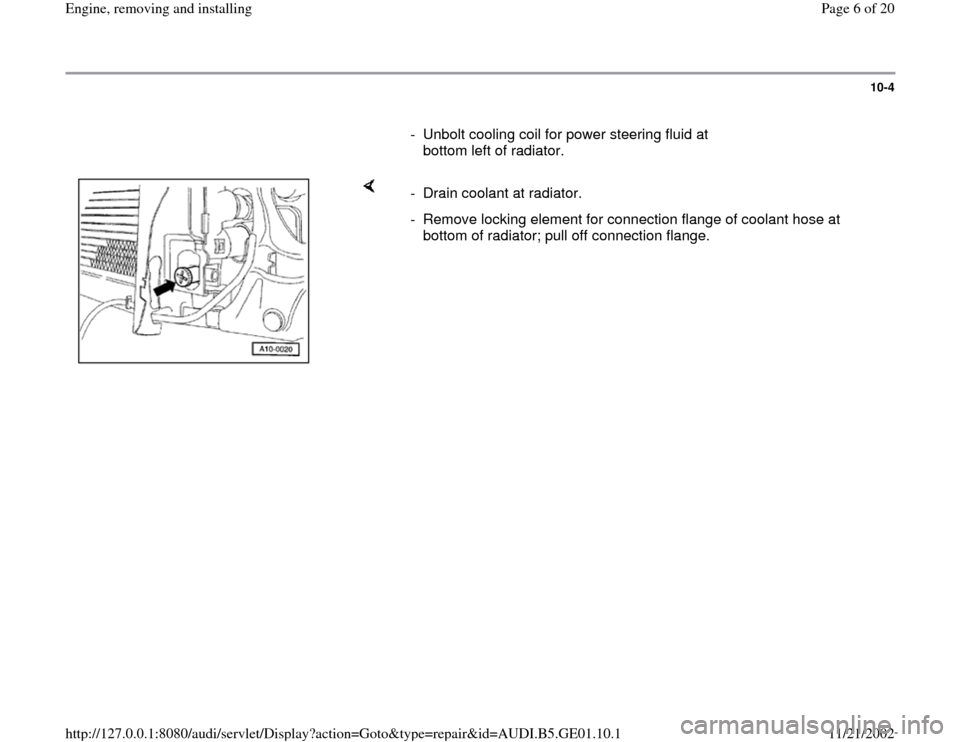
- Drain coolant at radiator.
- Remove locking element for connection flange of coolant hose at
bottom of radiator; pull off connection flange.
Pa
ge 6 of 20 En
gine, removin
g and installin
g
11/21/2002 htt
p://127.0.0.1:8080/audi/servlet/Dis
play?action=Goto&t
yp
e=re
pair&id=AUDI.B5.GE01.10.1
Page 12 of 20
- Remove starter, take off insulator at starter
positive (B+) connection, unbolt fixture at engine
block, disconnect ground wire from engine
support.
- Unscrew four engine mounting bolts.
Pa
ge 12 of 20 En
gine, removin
g and installin
g
11/21/2002 htt
p://127.0.0.1:8080/audi/servlet/Dis
play?action=Goto&t
yp
e=re
pair&id=AUDI.B5.GE01.10.1
Page 13 of 20
10-9
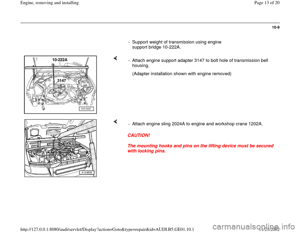
- Support weight of transmission using engine
support bridge 10-222A.
- Attach engine support adapter 3147 to bolt hole of transmission bell
housing.
(Adapter installation shown with engine removed)
CAUTION!
The mounting hooks and pins on the lifting device must be secured
with locking pins. - Attach engine sling 2024A to engine and workshop crane 1202A.
Pa
ge 13 of 20 En
gine, removin
g and installin
g
11/21/2002 htt
p://127.0.0.1:8080/audi/servlet/Dis
play?action=Goto&t
yp
e=re
pair&id=AUDI.B5.GE01.10.1
Page 14 of 20
10-10
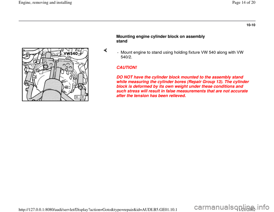
Mounting engine cylinder block on assembly
stand
CAUTION!
DO NOT have the cylinder block mounted to the assembly stand
while measuring the cylinder bores (Repair Group 13). The cylinder
block is deformed by its own weight under these conditions and
such stress will result in false measurements that are not accurate
after the tension has been relieved. - Mount engine to stand using holding fixture VW 540 along with VW
540/2.
Pa
ge 14 of 20 En
gine, removin
g and installin
g
11/21/2002 htt
p://127.0.0.1:8080/audi/servlet/Dis
play?action=Goto&t
yp
e=re
pair&id=AUDI.B5.GE01.10.1
Page 15 of 20
10-11
Installing
The engine is installed in the reverse order of
removal, with the addition of the following special
conditions and steps:
WARNING!
Do not re-use any fasteners that are worn or
deformed in normal use. Many fasteners are
designed to be used only once and become
unreliable and may fail when used a second
time. This includes, but is not limited to, nuts,
bolts, washers, self-locking nuts or bolts,
circlips and cotter pins. Always follow
recommendations given in this publication.
Always replace these fasteners with new
parts.
- Check that alignment sleeves for centering
engine and transmission are properly installed in
cylinder block. Install sleeves if necessary.
- Always install new seals and gaskets.
- Check centering of clutch disc, if necessary.
- Check clutch release bearing for wear and
replace if necessary.
Pa
ge 15 of 20 En
gine, removin
g and installin
g
11/21/2002 htt
p://127.0.0.1:8080/audi/servlet/Dis
play?action=Goto&t
yp
e=re
pair&id=AUDI.B5.GE01.10.1
Page 17 of 20
10-12
- Allow stop of torque support to move down onto
rubber block under its own weight; tighten bolts
to 45 Nm (33 ft lb).
- Align exhaust system free of stress Repair
Group 26.
- Adjust accelerator pedal cable Repair Group
20.
- Re-fill engine cooling system Repair Group
19.
- Drained coolant may only be re-used provided
the cylinder block or the cylinder head was not
replaced.
- Check oil level before starting engine.
- Short blocks are supplied without bushing in
crankshaft. For vehicles with automatic
transmission, tap bushing into place before
installing drive plate.
- Check reconditioned engines with manual
gearbox to determine whether needle bearing is
installed in crankshaft; install if necessary.
Pa
ge 17 of 20 En
gine, removin
g and installin
g
11/21/2002 htt
p://127.0.0.1:8080/audi/servlet/Dis
play?action=Goto&t
yp
e=re
pair&id=AUDI.B5.GE01.10.1