wiring AUDI A4 1998 B5 / 1.G AFC Engine Fuel Supply System Components Workshop Manual
[x] Cancel search | Manufacturer: AUDI, Model Year: 1998, Model line: A4, Model: AUDI A4 1998 B5 / 1.GPages: 24, PDF Size: 0.22 MB
Page 4 of 24
20-3
Safety precautions
WARNING!
When removing and installing the fuel pump
or fuel level sensor from a filled or partially
filled fuel tank:
BEFORE beginning repairs, the suction pipe
of an exhaust extraction system must be
located near the fuel tank opening so that
escaping fuel vapors can be immediately
carried away.
If no exhaust extraction system is available,
a radial fan (motor located outside airflow)
with volume of at least 15 m3/hr (9 cfm) may
be used.
Wear fuel-resistant gloves whenever working
with open parts of the fuel system.
Be sure the ignition is switched OFF, when:
Disconnecting fuel injection system wiring
Connecting or disconnecting test equipment
leads
BEFORE cranking the engine at starting RPM
Pa
ge 4 of 24 Fuel su
pp
ly system com
ponents, removin
g and installin
g
11/21/2002 htt
p://127.0.0.1:8080/audi/servlet/Dis
play?action=Goto&t
yp
e=re
pair&id=AUDI.B5.GE01.20.1
Page 10 of 24
20-6
Installing
_________________________________________________________
Front-wheel-drive vehicles:
All-wheel-drive vehicles:
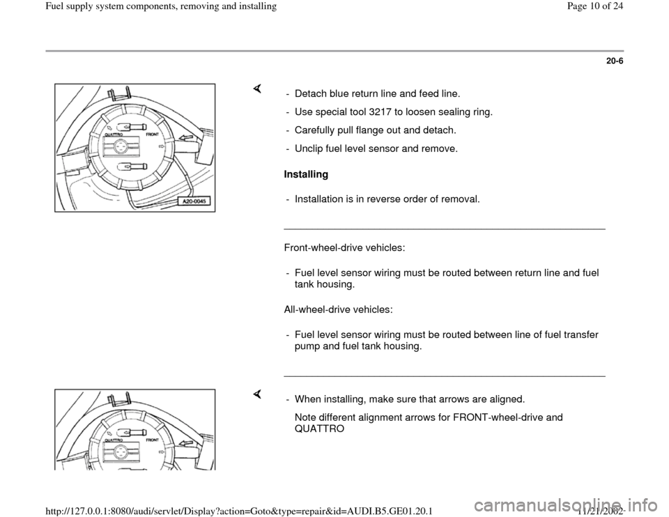
_________________________________________________________ - Detach blue return line and feed line.
- Use special tool 3217 to loosen sealing ring.
- Carefully pull flange out and detach.
- Unclip fuel level sensor and remove.
- Installation is in reverse order of removal.
- Fuel level sensor wiring must be routed between return line and fuel
tank housing.
- Fuel level sensor wiring must be routed between line of fuel transfer
pump and fuel tank housing.
- When installing, make sure that arrows are aligned.
Note different alignment arrows for FRONT-wheel-drive and
QUATTRO
Pa
ge 10 of 24 Fuel su
pp
ly system com
ponents, removin
g and installin
g
11/21/2002 htt
p://127.0.0.1:8080/audi/servlet/Dis
play?action=Goto&t
yp
e=re
pair&id=AUDI.B5.GE01.20.1
Page 13 of 24
20-8
Front-wheel-drive vehicles
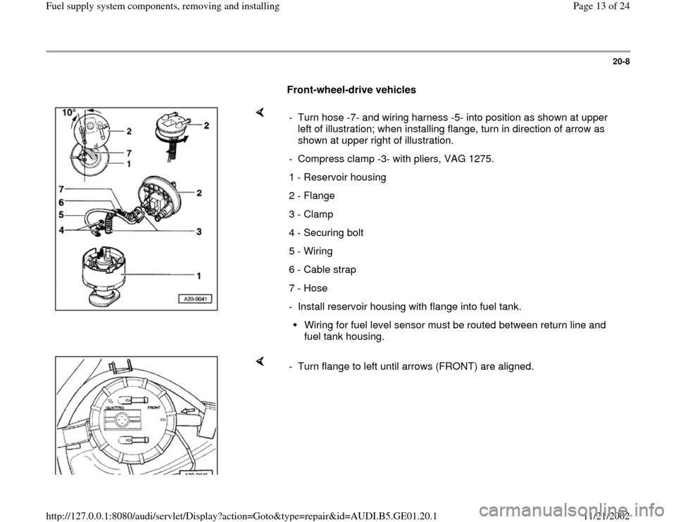
- Turn hose -7- and wiring harness -5- into position as shown at upper
left of illustration; when installing flange, turn in direction of arrow as
shown at upper right of illustration.
- Compress clamp -3- with pliers, VAG 1275.
1 - Reservoir housing
2 - Flange
3 - Clamp
4 - Securing bolt
5 - Wiring
6 - Cable strap
7 - Hose
- Install reservoir housing with flange into fuel tank.
Wiring for fuel level sensor must be routed between return line and
fuel tank housing.
- Turn flange to left until arrows (FRONT) are aligned.
Pa
ge 13 of 24 Fuel su
pp
ly system com
ponents, removin
g and installin
g
11/21/2002 htt
p://127.0.0.1:8080/audi/servlet/Dis
play?action=Goto&t
yp
e=re
pair&id=AUDI.B5.GE01.20.1
Page 14 of 24
20-9
All wheel-drive-vehicles
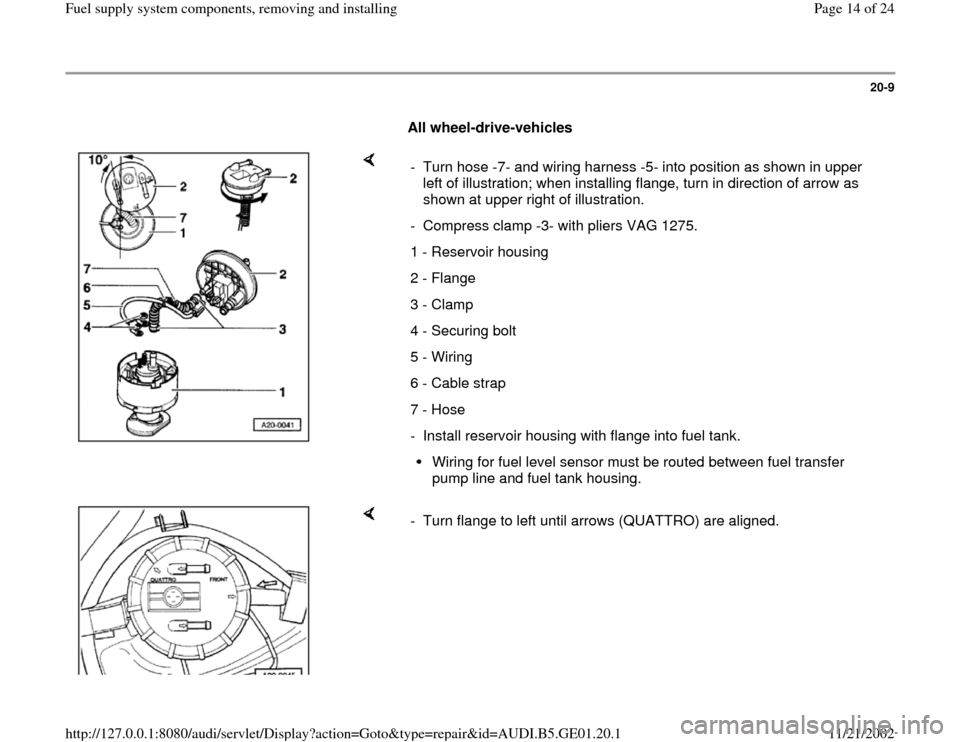
- Turn hose -7- and wiring harness -5- into position as shown in upper
left of illustration; when installing flange, turn in direction of arrow as
shown at upper right of illustration.
- Compress clamp -3- with pliers VAG 1275.
1 - Reservoir housing
2 - Flange
3 - Clamp
4 - Securing bolt
5 - Wiring
6 - Cable strap
7 - Hose
- Install reservoir housing with flange into fuel tank.
Wiring for fuel level sensor must be routed between fuel transfer
pump line and fuel tank housing.
- Turn flange to left until arrows (QUATTRO) are aligned.
Pa
ge 14 of 24 Fuel su
pp
ly system com
ponents, removin
g and installin
g
11/21/2002 htt
p://127.0.0.1:8080/audi/servlet/Dis
play?action=Goto&t
yp
e=re
pair&id=AUDI.B5.GE01.20.1
Page 17 of 24
20-11
- Supply voltage to fuel pump using VAG 1551
scan tool and "Output Diagnostic Test Mode"
function 03.
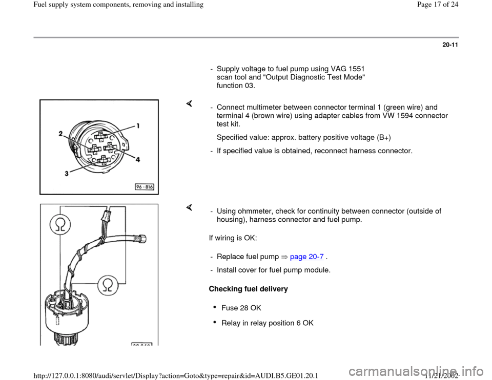
- Connect multimeter between connector terminal 1 (green wire) and
terminal 4 (brown wire) using adapter cables from VW 1594 connector
test kit.
Specified value: approx. battery positive voltage (B+)
- If specified value is obtained, reconnect harness connector.
If wiring is OK:
Checking fuel delivery - Using ohmmeter, check for continuity between connector (outside of
housing), harness connector and fuel pump.
- Replace fuel pump page 20
-7 .
- Install cover for fuel pump module.
Fuse 28 OK Relay in relay position 6 OK
Pa
ge 17 of 24 Fuel su
pp
ly system com
ponents, removin
g and installin
g
11/21/2002 htt
p://127.0.0.1:8080/audi/servlet/Dis
play?action=Goto&t
yp
e=re
pair&id=AUDI.B5.GE01.20.1