light AUDI A4 1998 B5 / 1.G AHA Engine Multiport Fuel Injection And Ignition System Workshop Manual
[x] Cancel search | Manufacturer: AUDI, Model Year: 1998, Model line: A4, Model: AUDI A4 1998 B5 / 1.GPages: 166, PDF Size: 0.91 MB
Page 31 of 166
24-24
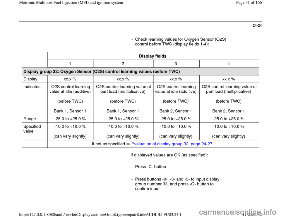
- Check learning values for Oxygen Sensor (O2S)
control before TWC (display fields 1-4):
Display fields
1 2 3 4
Display group 32: Oxygen Sensor (O2S) control learning values (before TWC)
Display xx.x % xx.x % xx.x % xx.x %
Indicates O2S control learning
value at idle (additive)
(before TWC)
Bank 1, Sensor 1 O2S control learning value at
part load (multiplicative)
(before TWC)
Bank 1, Sensor 1 O2S control learning
value at idle (additive)
(before TWC)
Bank 2, Sensor 1 O2S control learning value at
part load (multiplicative)
(before TWC)
Bank 2, Sensor 1
Range -25.0 to +25.0 % -25.0 to +25.0 % -25.0 to +25.0 % -25.0 to +25.0 %
Specified
value -10.0 to +10.0 %
(can vary slightly) -10.0 to +10.0 %
(can vary slightly) -10.0 to +10.0 %
(can vary slightly) -10.0 to +10.0 %
(can vary slightly)
If not as specified Evaluation of display group 32, page 24
-27
If displayed values are OK (as specified):
- Press -C- button.
- Press buttons -0-, -3- and -3- to input display
group number 33, and press -Q- button to
confirm input.
Pa
ge 31 of 166 Motronic Multi
port Fuel In
jection
(MFI
) and i
gnition s
ystem
11/23/2002 htt
p://127.0.0.1:8080/audi/servlet/Dis
play?action=Goto&t
yp
e=re
pair&id=AUDI.B5.FU03.24.1
Page 57 of 166
24-44
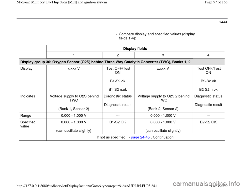
- Compare display and specified values (display
fields 1-4):
Display fields
1 2 3 4
Display group 36: Oxygen Sensor (O2S) behind Three Way Catalytic Converter (TWC), Banks 1, 2
Display x.xxx V Test OFF/Test
ON
B1-S2 ok
B1-S2 n.ok x.xxx V Test OFF/Test
ON
B2-S2 ok
B2-S2 n.ok
Indicates Voltage supply to O2S behind
TWC
(Bank 1, Sensor 2) Diagnostic status
Diagnostic result Voltage supply to O2S 2 behind
TWC
(Bank 2, Sensor 2) Diagnostic status
Diagnostic result
Range 0.000 - 1.000 V --- 0.000 - 1.000 V ---
Specified
value 0.000 - 1.000 V
(can oscillate slightly) B1-S2 OK 0.000 - 1.000 V
(can oscillate slightly) B2-S2 OK
If not as specified page 24
-45
, Continuation
Pa
ge 57 of 166 Motronic Multi
port Fuel In
jection
(MFI
) and i
gnition s
ystem
11/23/2002 htt
p://127.0.0.1:8080/audi/servlet/Dis
play?action=Goto&t
yp
e=re
pair&id=AUDI.B5.FU03.24.1
Page 88 of 166
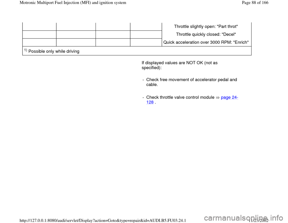
Throttle slightly open: "Part throt"
Throttle quickly closed: "Decel"
Quick acceleration over 3000 RPM: "Enrich" 1) Possible only while driving
If displayed values are NOT OK (not as
specified):
- Check free movement of accelerator pedal and
cable.
- Check throttle valve control module page 24
-
128
.
Pa
ge 88 of 166 Motronic Multi
port Fuel In
jection
(MFI
) and i
gnition s
ystem
11/23/2002 htt
p://127.0.0.1:8080/audi/servlet/Dis
play?action=Goto&t
yp
e=re
pair&id=AUDI.B5.FU03.24.1
Page 121 of 166
24-95
Fuel pump relay and connections,
checking
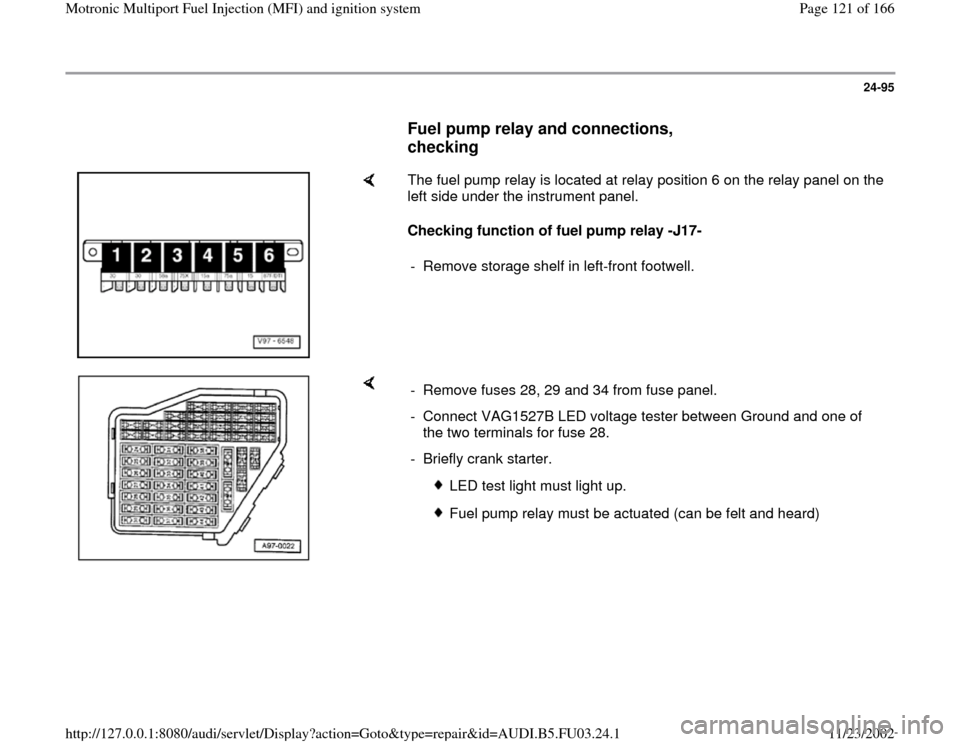
The fuel pump relay is located at relay position 6 on the relay panel on the
left side under the instrument panel.
Checking function of fuel pump relay -J17-
- Remove storage shelf in left-front footwell.
- Remove fuses 28, 29 and 34 from fuse panel.
- Connect VAG1527B LED voltage tester between Ground and one of
the two terminals for fuse 28.
- Briefly crank starter.
LED test light must light up.
Fuel pump relay must be actuated (can be felt and heard)
Pa
ge 121 of 166 Motronic Multi
port Fuel In
jection
(MFI
) and i
gnition s
ystem
11/23/2002 htt
p://127.0.0.1:8080/audi/servlet/Dis
play?action=Goto&t
yp
e=re
pair&id=AUDI.B5.FU03.24.1
Page 122 of 166
24-96
If the fuel pump does not respond:
- Check fuel pump relay actuation page 24
-
99
.
If the LED test light does not light up:
- Repeat test at other terminal of fuse 28.
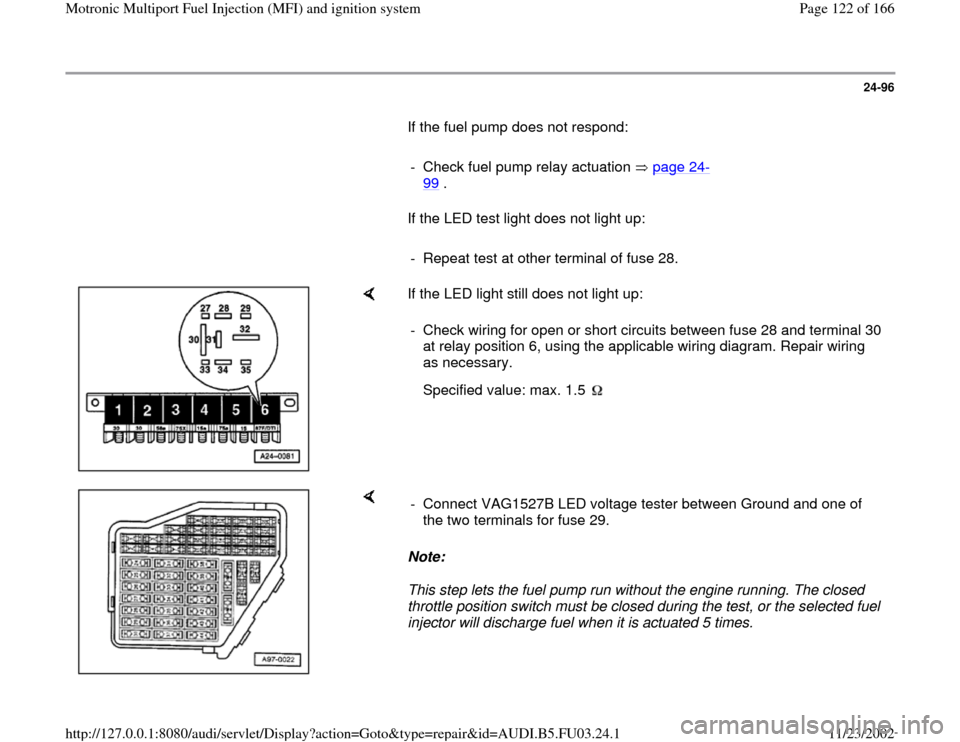
If the LED light still does not light up:
- Check wiring for open or short circuits between fuse 28 and terminal 30
at relay position 6, using the applicable wiring diagram. Repair wiring
as necessary.
Specified value: max. 1.5
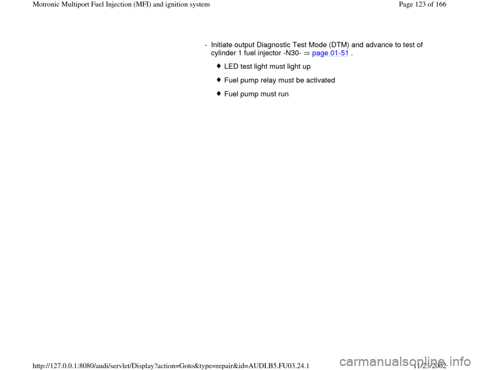
Note:
This step lets the fuel pump run without the engine running. The closed
throttle position switch must be closed during the test, or the selected fuel
injector will discharge fuel when it is actuated 5 times. - Connect VAG1527B LED voltage tester between Ground and one of
the two terminals for fuse 29.
Pa
ge 122 of 166 Motronic Multi
port Fuel In
jection
(MFI
) and i
gnition s
ystem
11/23/2002 htt
p://127.0.0.1:8080/audi/servlet/Dis
play?action=Goto&t
yp
e=re
pair&id=AUDI.B5.FU03.24.1
Page 123 of 166
- Initiate output Diagnostic Test Mode (DTM) and advance to test of
cylinder 1 fuel injector -N30- page 01
-51
.
LED test light must light up
Fuel pump relay must be activated
Fuel pump must run
Pa
ge 123 of 166 Motronic Multi
port Fuel In
jection
(MFI
) and i
gnition s
ystem
11/23/2002 htt
p://127.0.0.1:8080/audi/servlet/Dis
play?action=Goto&t
yp
e=re
pair&id=AUDI.B5.FU03.24.1
Page 124 of 166
24-97
If the LED test light does not light up:
- Repeat test at other terminal of fuse 29.
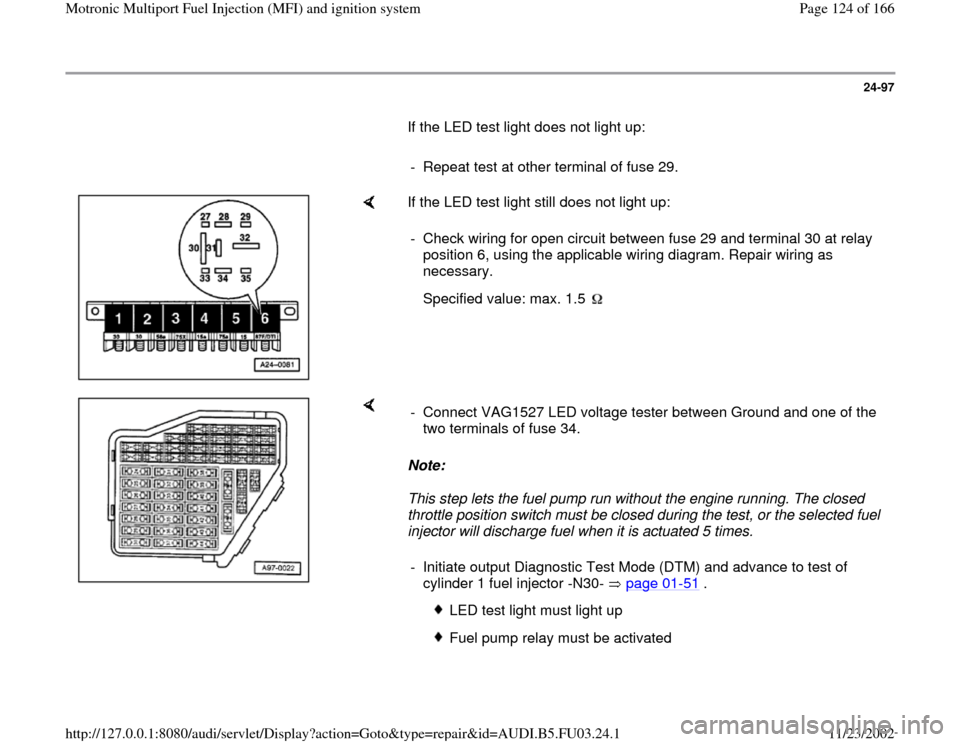
If the LED test light still does not light up:
- Check wiring for open circuit between fuse 29 and terminal 30 at relay
position 6, using the applicable wiring diagram. Repair wiring as
necessary.
Specified value: max. 1.5
Note:
This step lets the fuel pump run without the engine running. The closed
throttle position switch must be closed during the test, or the selected fuel
injector will discharge fuel when it is actuated 5 times. - Connect VAG1527 LED voltage tester between Ground and one of the
two terminals of fuse 34.
- Initiate output Diagnostic Test Mode (DTM) and advance to test of
cylinder 1 fuel injector -N30- page 01
-51
.
LED test light must light up
Fuel pump relay must be activated
Pa
ge 124 of 166 Motronic Multi
port Fuel In
jection
(MFI
) and i
gnition s
ystem
11/23/2002 htt
p://127.0.0.1:8080/audi/servlet/Dis
play?action=Goto&t
yp
e=re
pair&id=AUDI.B5.FU03.24.1
Page 126 of 166
24-98
If the LED test light does not light up:
- Repeat test at other terminal of fuse 34.
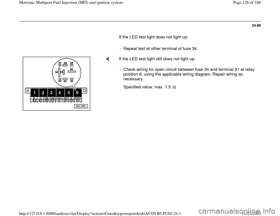
If the LED test light still does not light up:
- Check wiring for open circuit between fuse 34 and terminal 31 at relay
position 6, using the applicable wiring diagram. Repair wiring as
necessary.
Specified value: max. 1.5
Pa
ge 126 of 166 Motronic Multi
port Fuel In
jection
(MFI
) and i
gnition s
ystem
11/23/2002 htt
p://127.0.0.1:8080/audi/servlet/Dis
play?action=Goto&t
yp
e=re
pair&id=AUDI.B5.FU03.24.1
Page 128 of 166
24-100
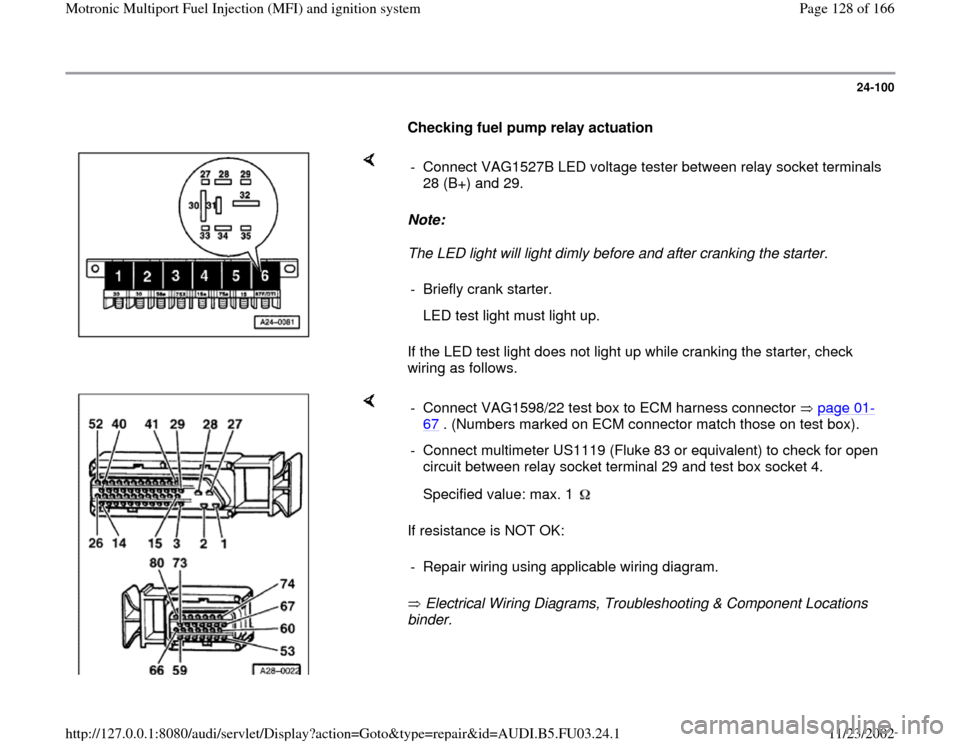
Checking fuel pump relay actuation
Note:
The LED light will light dimly before and after cranking the starter.
If the LED test light does not light up while cranking the starter, check
wiring as follows. - Connect VAG1527B LED voltage tester between relay socket terminals
28 (B+) and 29.
- Briefly crank starter.
LED test light must light up.
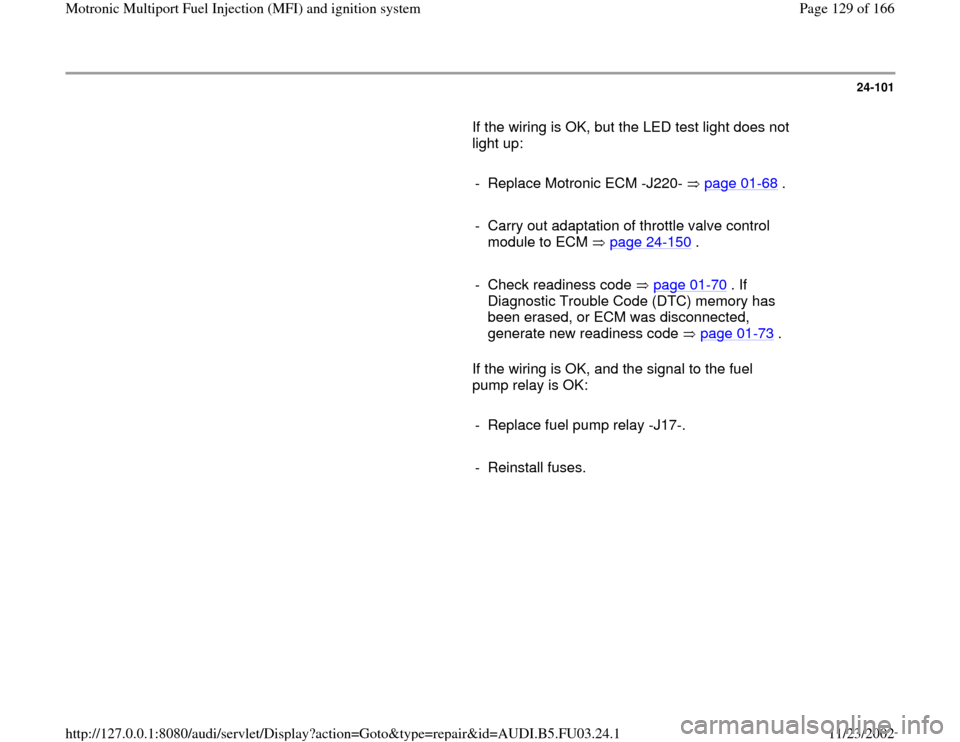
If resistance is NOT OK:
Electrical Wiring Diagrams, Troubleshooting & Component Locations
binder. - Connect VAG1598/22 test box to ECM harness connector page 01
-
67
. (Numbers marked on ECM connector match those on test box).
- Connect multimeter US1119 (Fluke 83 or equivalent) to check for open
circuit between relay socket terminal 29 and test box socket 4.
Specified value: max. 1 - Repair wiring using applicable wiring diagram.
Pa
ge 128 of 166 Motronic Multi
port Fuel In
jection
(MFI
) and i
gnition s
ystem
11/23/2002 htt
p://127.0.0.1:8080/audi/servlet/Dis
play?action=Goto&t
yp
e=re
pair&id=AUDI.B5.FU03.24.1
Page 129 of 166
24-101
If the wiring is OK, but the LED test light does not
light up:
- Replace Motronic ECM -J220- page 01
-68
.
- Carry out adaptation of throttle valve control
module to ECM page 24
-150
.
- Check readiness code page 01
-70
. If
Diagnostic Trouble Code (DTC) memory has
been erased, or ECM was disconnected,
generate new readiness code page 01
-73
.
If the wiring is OK, and the signal to the fuel
pump relay is OK:
- Replace fuel pump relay -J17-.
- Reinstall fuses.
Pa
ge 129 of 166 Motronic Multi
port Fuel In
jection
(MFI
) and i
gnition s
ystem
11/23/2002 htt
p://127.0.0.1:8080/audi/servlet/Dis
play?action=Goto&t
yp
e=re
pair&id=AUDI.B5.FU03.24.1