ECU AUDI A4 1998 B5 / 1.G APB Engine Ignition System Checking
[x] Cancel search | Manufacturer: AUDI, Model Year: 1998, Model line: A4, Model: AUDI A4 1998 B5 / 1.GPages: 64, PDF Size: 0.37 MB
Page 38 of 64

28-34
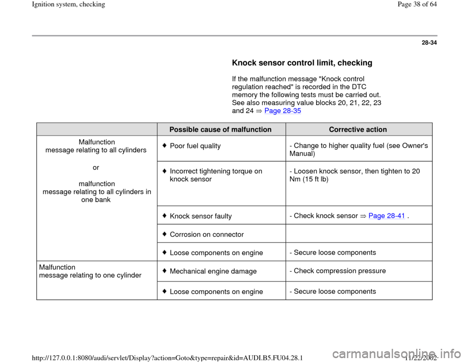
Knock sensor control limit, checking
If the malfunction message "Knock control
regulation reached" is recorded in the DTC
memory the following tests must be carried out.
See also measuring value blocks 20, 21, 22, 23
and 24 Page 28
-35
Possible cause of malfunction
Corrective action
Malfunction
message relating to all cylinders
Poor fuel quality- Change to higher quality fuel (see Owner's
Manual)
or
malfunction
message relating to all cylinders in
one bank Incorrect tightening torque on
knock sensor - Loosen knock sensor, then tighten to 20
Nm (15 ft lb)
Knock sensor faulty- Check knock sensor Page 28
-41
.
Corrosion on connector
Loose components on engine- Secure loose components
Malfunction
message relating to one cylinder Mechanical engine damage- Check compression pressure
Loose components on engine- Secure loose components
Pa
ge 38 of 64 I
gnition s
ystem, checkin
g
11/22/2002 htt
p://127.0.0.1:8080/audi/servlet/Dis
play?action=Goto&t
yp
e=re
pair&id=AUDI.B5.FU04.28.1
Page 46 of 64

28-41
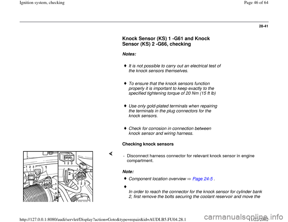
Knock Sensor (KS) 1 -G61 and Knock
Sensor (KS) 2 -G66, checking
Notes:
It is not possible to carry out an electrical test of
the knock sensors themselves.
To ensure that the knock sensors function
properly it is important to keep exactly to the
specified tightening torque of 20 Nm (15 ft lb)
Use only gold-plated terminals when repairing
the terminals in the plug connectors for the
knock sensors.
Check for corrosion in connection between
knock sensor and wiring harness.
Checking knock sensors
Note: - Disconnect harness connector for relevant knock sensor in engine
compartment.
Component location overview Page 24
-5 .
In order to reach the connector for the knock sensor for cylinder bank
2, first remove the bolts securing the coolant reservoir and move the
Pa
ge 46 of 64 I
gnition s
ystem, checkin
g
11/22/2002 htt
p://127.0.0.1:8080/audi/servlet/Dis
play?action=Goto&t
yp
e=re
pair&id=AUDI.B5.FU04.28.1
Page 58 of 64

28-51
Read Measuring Value Block 93
1
2
3
4
Indicated on display
- Check specified display values for Hall sensors.
Display fields
1 2 3 4
Display Group 093: Phase positions of Hall sensors (Bank 1 and Bank 2) with engine idling
Display xxx RPM xx %
0 6 KW
0 6 KW
Indicates Engine
speed
(RPM) Engine
load Phase position
Bank 1 Phase position
Bank 2
Work
range min.: 750
RPM
max.: 6800
RPM min.: 15
%
max.:
175 % -20.3 to 14.8 KW
-20.3 to 14.8 KW
Specified
value 750 - 850
RPM
0 6 KW
0 6 KW
Note
If readouts do not match specifications, unbolt Hall sensor and check whether
rotor ring is properly mounted on camshaft. If it is incorrectly mounted, the
locating lug will be flattened when the securing bolt is tightened. Also check
valve timing.
Repair Manual, 2.7 Liter V6 5V BiTurbo Engine Mechanical, Engine Code(s): APB,
Repair Group 13, Crankcase ventilation, Ribbed belt removing and installing, Timing belt removing and installing
Pa
ge 58 of 64 I
gnition s
ystem, checkin
g
11/22/2002 htt
p://127.0.0.1:8080/audi/servlet/Dis
play?action=Goto&t
yp
e=re
pair&id=AUDI.B5.FU04.28.1