battery AUDI A4 1998 B5 / 1.G APB Engine Ignition System Checking
[x] Cancel search | Manufacturer: AUDI, Model Year: 1998, Model line: A4, Model: AUDI A4 1998 B5 / 1.GPages: 64, PDF Size: 0.37 MB
Page 1 of 64
28-1
Ignition system, checking
General notes on ignition system
Always switch off the ignition before connecting
or disconnecting the battery, otherwise the
engine control module may be damaged.
The engine control module is equipped with On
Board Diagnostic (OBD).
For trouble-free operation of the electrical
components a voltage of at least 11.5 V is
necessary.
During some of the tests it is possible that the
control module will detect and record a
malfunction. The DTC memory must therefore
be checked and if necessary erased when all
tests and repair work have been completed.
After completing troubleshooting, repairs or
component tests, it is possible that the engine
will start, run for a short period and then cut out.
If this happens it may be that the immobilizer is
blocking the engine control module. In such
cases the DTC memory must be checked and if
necessary the control module must be adapted.
Pa
ge 1 of 64 I
gnition s
ystem, checkin
g
11/22/2002 htt
p://127.0.0.1:8080/audi/servlet/Dis
play?action=Goto&t
yp
e=re
pair&id=AUDI.B5.FU04.28.1
Page 2 of 64
28-2
Safety precautions
To prevent injuries to persons and/or damage to
the fuel injection and ignition system, the
following must be noted:
WARNING!
Be alert when working on or near the engine.
High ignition secondary voltage can cause
serious personal injury and damage vehicle
components.
DO NOT touch or disconnect ignition wiring
when the engine is running or being turned
at starter speed.
DO NOT operate the starter if fuel injectors
are removed.
Always switch off the ignition before
connecting or disconnecting the battery,
otherwise the engine control module may be
damaged.
The ignition must be switched off before
connecting or disconnecting injection or
ignition system wiring or tester cables.
In order to run the engine at starting speed
Pa
ge 2 of 64 I
gnition s
ystem, checkin
g
11/22/2002 htt
p://127.0.0.1:8080/audi/servlet/Dis
play?action=Goto&t
yp
e=re
pair&id=AUDI.B5.FU04.28.1
Page 4 of 64
28-3
CAUTION!
Before disconnecting the battery:
Stop the engine.
Be sure of proper radio code (for vehicles
equipped with coded anti-theft radio).
When connecting and disconnecting
electrical test equipment (LED voltage tester,
multi meter, etc.):
Be sure the ignition is switched OFF.
Use correct adapters from VAG1594
connector test kit
Pa
ge 4 of 64 I
gnition s
ystem, checkin
g
11/22/2002 htt
p://127.0.0.1:8080/audi/servlet/Dis
play?action=Goto&t
yp
e=re
pair&id=AUDI.B5.FU04.28.1
Page 9 of 64
28-8
If malfunction remains at the same cylinder.
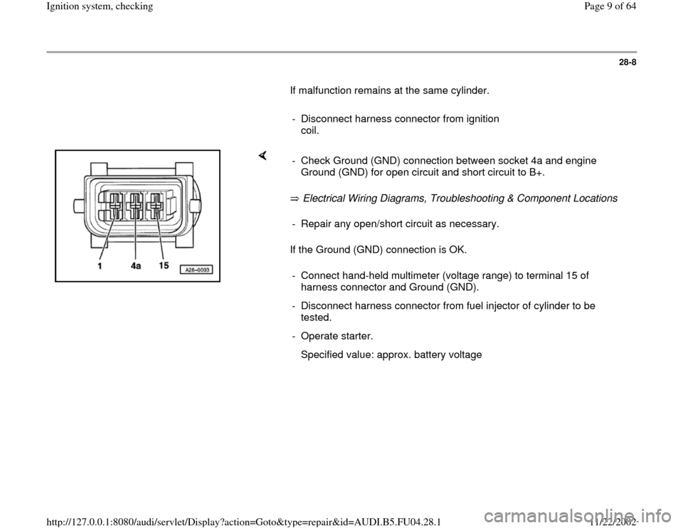
- Disconnect harness connector from ignition
coil.
Electrical Wiring Diagrams, Troubleshooting & Component Locations
If the Ground (GND) connection is OK. - Check Ground (GND) connection between socket 4a and engine
Ground (GND) for open circuit and short circuit to B+. - Repair any open/short circuit as necessary.
- Connect hand-held multimeter (voltage range) to terminal 15 of
harness connector and Ground (GND).
- Disconnect harness connector from fuel injector of cylinder to be
tested.
- Operate starter.
Specified value: approx. battery voltage
Pa
ge 9 of 64 I
gnition s
ystem, checkin
g
11/22/2002 htt
p://127.0.0.1:8080/audi/servlet/Dis
play?action=Goto&t
yp
e=re
pair&id=AUDI.B5.FU04.28.1
Page 16 of 64

28-14
- Rectify any open/short circuit as necessary.
If no wiring malfunction is detected:
- Connect 4-pin connectors to power output
stages.
- Disconnect 3-pin connectors from power output
stages.
- Connect diode test lamp VAG1527 to battery
(B+) and to one of the 3 terminals on power
output stage.
- Operate starter for few seconds.
The diode test lamp should flash.
- Carry out test with all 3 terminals on each of the
3-pin connectors for the power output stages.
The diode test lamp should flash each time.
Pa
ge 16 of 64 I
gnition s
ystem, checkin
g
11/22/2002 htt
p://127.0.0.1:8080/audi/servlet/Dis
play?action=Goto&t
yp
e=re
pair&id=AUDI.B5.FU04.28.1
Page 17 of 64

28-15
If the diode test lamp does not flash when testing
one or more of the contacts:
Check the Ground (GND) connections for the
power output stages as follows:
- Disconnect 4-pin harness connectors from
power output stages.
- Connect diode test lamp VAG1527 to battery
(B+) and terminal 2 of each of the 4-pin
connectors in turn.
The diode test lamp should light up.
Pa
ge 17 of 64 I
gnition s
ystem, checkin
g
11/22/2002 htt
p://127.0.0.1:8080/audi/servlet/Dis
play?action=Goto&t
yp
e=re
pair&id=AUDI.B5.FU04.28.1
Page 20 of 64
28-18
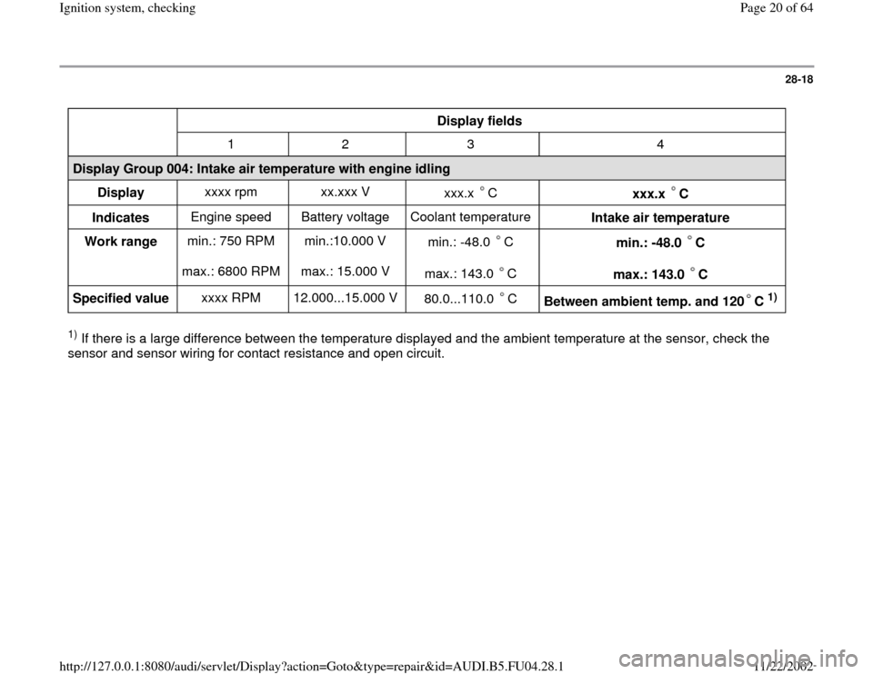
Display fields
1 2 3 4
Display Group 004: Intake air temperature with engine idling
Display xxxx rpm xx.xxx V
xxx.x C
xxx.x C
Indicates Engine speed Battery voltage Coolant temperature
Intake air temperature
Work range min.: 750 RPM
max.: 6800 RPM min.:10.000 V
max.: 15.000 V min.: -48.0 C
max.: 143.0 C
min.: -48.0 C
max.: 143.0 C
Specified value xxxx RPM 12.000...15.000 V
80.0...110.0 C
Between ambient temp. and 120 C
1)
1) If there is a large difference between the temperature displayed and the ambient temperature at the sensor, check the
sensor and sensor wiring for contact resistance and open circuit.
Pa
ge 20 of 64 I
gnition s
ystem, checkin
g
11/22/2002 htt
p://127.0.0.1:8080/audi/servlet/Dis
play?action=Goto&t
yp
e=re
pair&id=AUDI.B5.FU04.28.1
Page 30 of 64
28-27
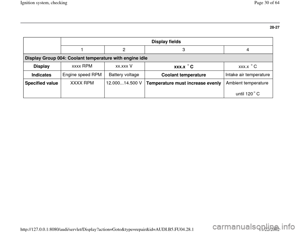
Display fields
1 2 3 4
Display Group 004: Coolant temperature with engine idle
Display xxxx RPM xx.xxx V
xxx.x C
xxx.x C
Indicates Engine speed RPM Battery voltage
Coolant temperature Intake air temperature
Specified value XXXX RPM 12.000...14.500 V
Temperature must increase evenly Ambient temperature
until 120 C
Pa
ge 30 of 64 I
gnition s
ystem, checkin
g
11/22/2002 htt
p://127.0.0.1:8080/audi/servlet/Dis
play?action=Goto&t
yp
e=re
pair&id=AUDI.B5.FU04.28.1
Page 35 of 64
28-32
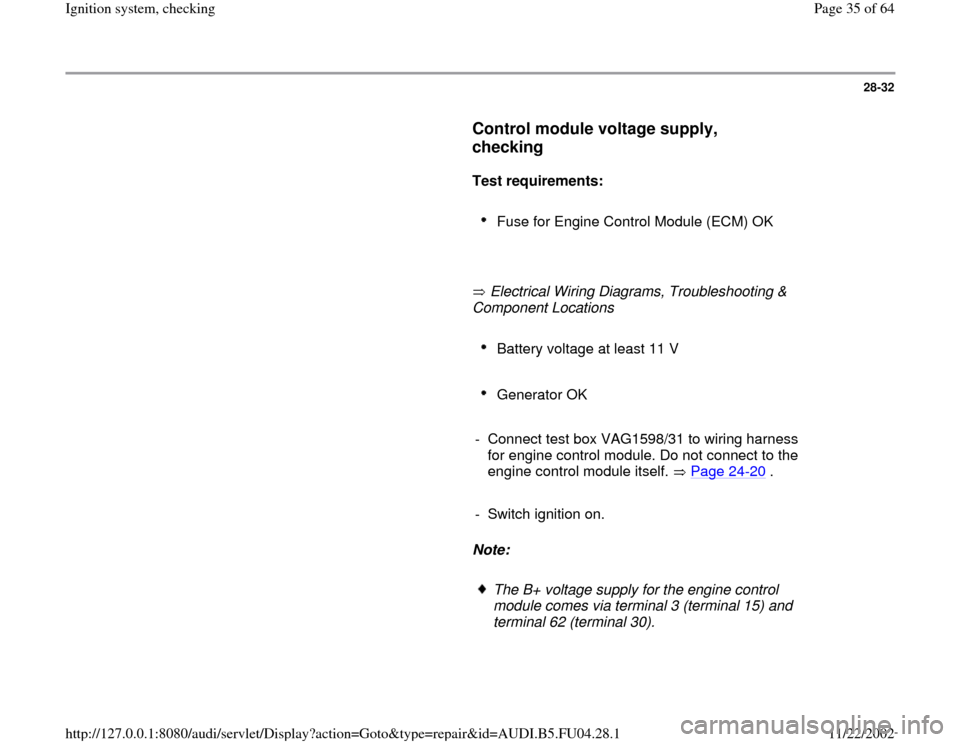
Control module voltage supply,
checking
Test requirements:
Fuse for Engine Control Module (ECM) OK
Electrical Wiring Diagrams, Troubleshooting &
Component Locations
Battery voltage at least 11 V
Generator OK
- Connect test box VAG1598/31 to wiring harness
for engine control module. Do not connect to the
engine control module itself. Page 24
-20
.
- Switch ignition on.
Note:
The B+ voltage supply for the engine control
module comes via terminal 3 (terminal 15) and
terminal 62 (terminal 30).
Pa
ge 35 of 64 I
gnition s
ystem, checkin
g
11/22/2002 htt
p://127.0.0.1:8080/audi/servlet/Dis
play?action=Goto&t
yp
e=re
pair&id=AUDI.B5.FU04.28.1
Page 37 of 64
28-33
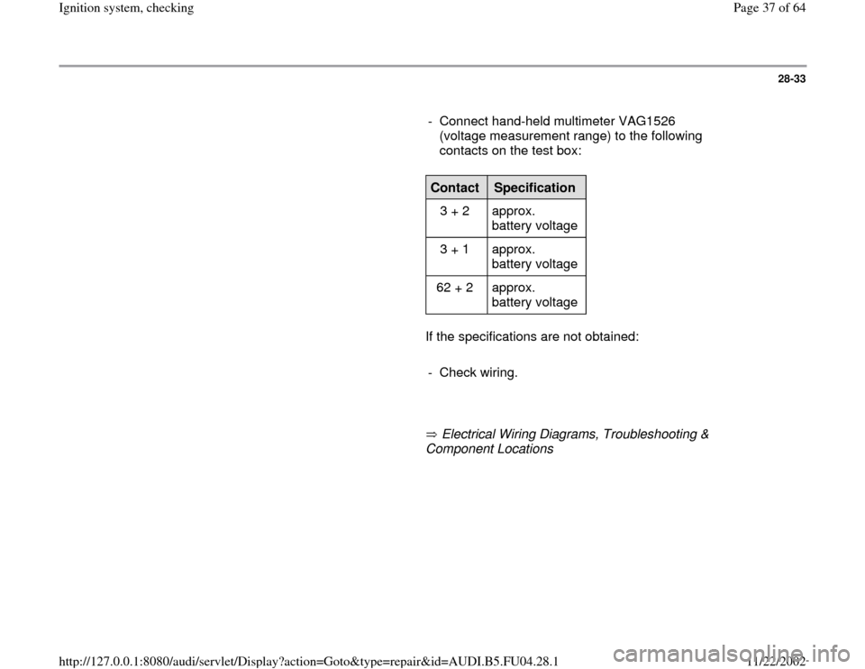
- Connect hand-held multimeter VAG1526
(voltage measurement range) to the following
contacts on the test box:
Contact
Specification
3 + 2 approx.
battery voltage
3 + 1 approx.
battery voltage
62 + 2 approx.
battery voltage
If the specifications are not obtained:
- Check wiring.
Electrical Wiring Diagrams, Troubleshooting &
Component Locations
Pa
ge 37 of 64 I
gnition s
ystem, checkin
g
11/22/2002 htt
p://127.0.0.1:8080/audi/servlet/Dis
play?action=Goto&t
yp
e=re
pair&id=AUDI.B5.FU04.28.1