fuel pump AUDI A4 1998 B5 / 1.G APB Engine Motronic Multiport Fuel Injection System Servising Workshop Manual
[x] Cancel search | Manufacturer: AUDI, Model Year: 1998, Model line: A4, Model: AUDI A4 1998 B5 / 1.GPages: 90, PDF Size: 0.84 MB
Page 7 of 90
24-5
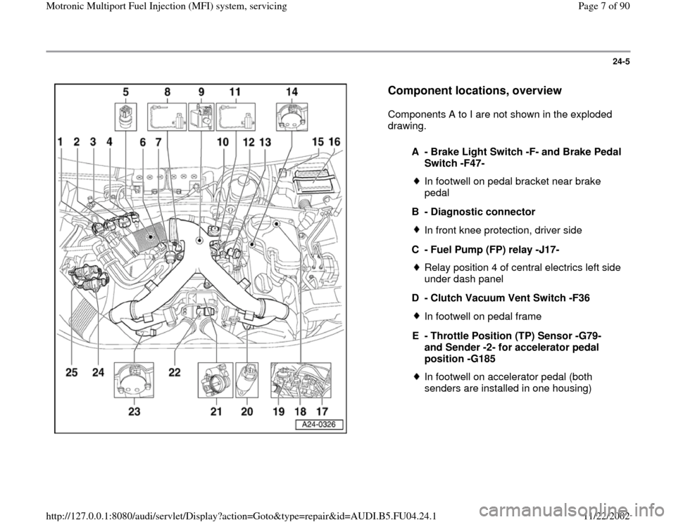
Component locations, overview
Components A to I are not shown in the exploded
drawing.
A - Brake Light Switch -F- and Brake Pedal
Switch -F47-
In footwell on pedal bracket near brake
pedal
B - Diagnostic connectorIn front knee protection, driver side
C - Fuel Pump (FP) relay -J17-Relay position 4 of central electrics left side
under dash panel
D - Clutch Vacuum Vent Switch -F36In footwell on pedal frame
E - Throttle Position (TP) Sensor -G79-
and Sender -2- for accelerator pedal
position -G185 In footwell on accelerator pedal (both
senders are installed in one housing)
Pa
ge 7 of 90 Motronic Multi
port Fuel In
jection
(MFI
) system, servicin
g
11/22/2002 htt
p://127.0.0.1:8080/audi/servlet/Dis
play?action=Goto&t
yp
e=re
pair&id=AUDI.B5.FU04.24.1
Page 8 of 90
24-6
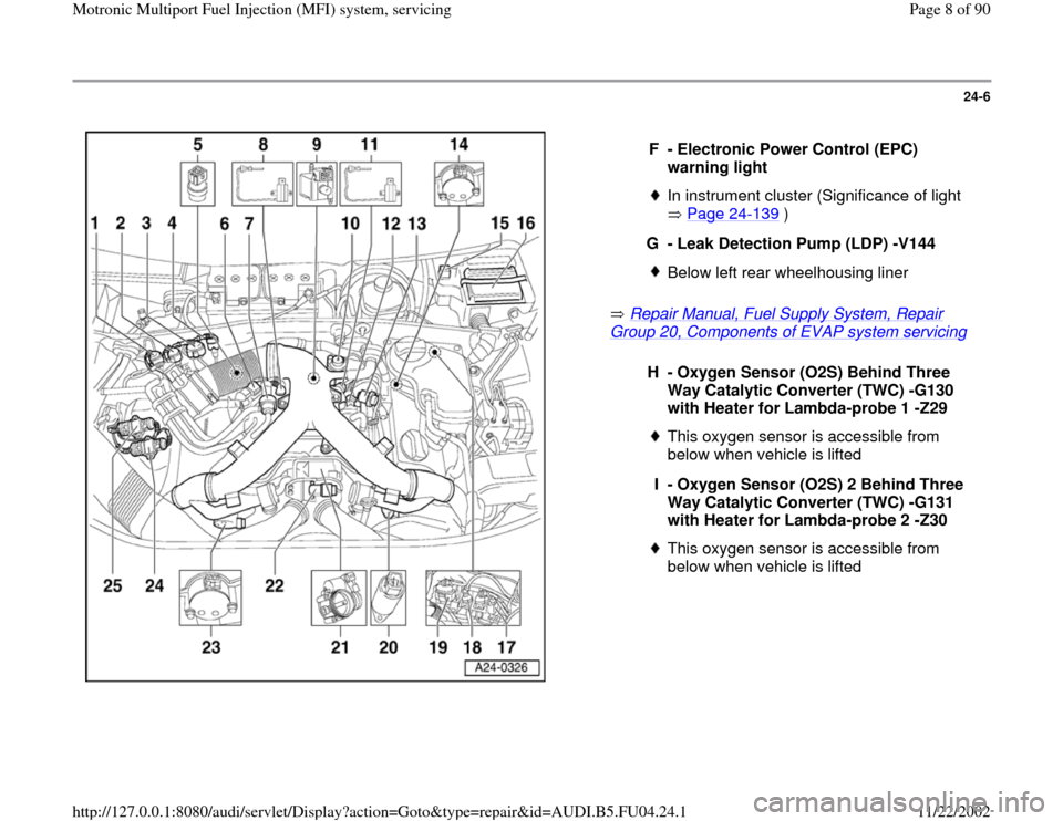
Repair Manual, Fuel Supply System, Repair
Group 20, Components of EVAP system servicing
F - Electronic Power Control (EPC)
warning light
In instrument cluster (Significance of light
Page 24
-139
)
G - Leak Detection Pump (LDP) -V144
Below left rear wheelhousing liner
H - Oxygen Sensor (O2S) Behind Three
Way Catalytic Converter (TWC) -G130
with Heater for Lambda-probe 1 -Z29
This oxygen sensor is accessible from
below when vehicle is lifted
I - Oxygen Sensor (O2S) 2 Behind Three
Way Catalytic Converter (TWC) -G131
with Heater for Lambda-probe 2 -Z30 This oxygen sensor is accessible from
below when vehicle is lifted
Pa
ge 8 of 90 Motronic Multi
port Fuel In
jection
(MFI
) system, servicin
g
11/22/2002 htt
p://127.0.0.1:8080/audi/servlet/Dis
play?action=Goto&t
yp
e=re
pair&id=AUDI.B5.FU04.24.1
Page 10 of 90
24-8
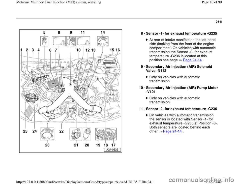
8 -
Sensor -1- for exhaust temperature -G235
At rear of intake manifold on the left-hand
side (looking from the front of the engine
compartment) On vehicles with automatic
transmission the Sensor -2- for exhaust
temperature -G236 is located at this
position see page Page 24
-14
.
9 -
Secondary Air Injection (AIR) Solenoid
Valve -N112
Only on vehicles with automatic
transmission
10 -
Secondary Air Injection (AIR) Pump Motor
-V101 Only on vehicles with automatic
transmission
11 -
Sensor -2- for exhaust temperature -G236 On vehicles with automatic transmission
the sensor is located with Sensor -1- for
exhaust temperature -G235 at Position -8-.
Both sensors are located behind each
other Page 24
-14
.
Pa
ge 10 of 90 Motronic Multi
port Fuel In
jection
(MFI
) system, servicin
g
11/22/2002 htt
p://127.0.0.1:8080/audi/servlet/Dis
play?action=Goto&t
yp
e=re
pair&id=AUDI.B5.FU04.24.1
Page 11 of 90
24-9
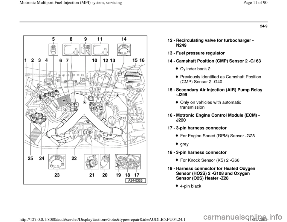
12 -
Recirculating valve for turbocharger -
N249
13 -
Fuel pressure regulator
14 -
Camshaft Position (CMP) Sensor 2 -G163
Cylinder bank 2Previously identified as Camshaft Position
(CMP) Sensor 2 -G40
15 -
Secondary Air Injection (AIR) Pump Relay
-J299 Only on vehicles with automatic
transmission
16 -
Motronic Engine Control Module (ECM) -
J220
17 -
3-pin harness connector For Engine Speed (RPM) Sensor -G28grey
18 -
3-pin harness connector For Knock Sensor (KS) 2 -G66
19 -
Harness connector for Heated Oxygen
Sensor (HO2S) 2 -G108 and Oxygen
Sensor (O2S) Heater -Z28 4-pin black
Pa
ge 11 of 90 Motronic Multi
port Fuel In
jection
(MFI
) system, servicin
g
11/22/2002 htt
p://127.0.0.1:8080/audi/servlet/Dis
play?action=Goto&t
yp
e=re
pair&id=AUDI.B5.FU04.24.1
Page 17 of 90
24-15
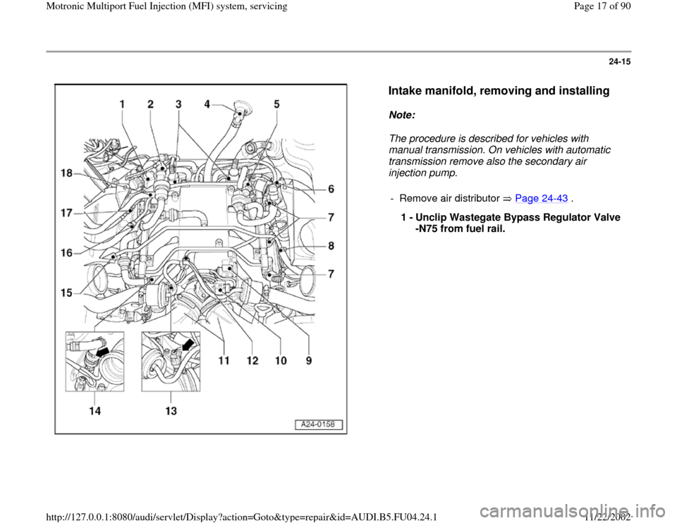
Intake manifold, removing and installing
Note:
The procedure is described for vehicles with
manual transmission. On vehicles with automatic
transmission remove also the secondary air
injection pump.
- Remove air distributor Page 24
-43
.
1 -
Unclip Wastegate Bypass Regulator Valve
-N75 from fuel rail.
Pa
ge 17 of 90 Motronic Multi
port Fuel In
jection
(MFI
) system, servicin
g
11/22/2002 htt
p://127.0.0.1:8080/audi/servlet/Dis
play?action=Goto&t
yp
e=re
pair&id=AUDI.B5.FU04.24.1
Page 38 of 90
24-33
Fuel pressure regulator and residual
fuel pressure, checking
Requirements
Fuel pump relay OK
Fuel pump OK
Fuel filter OK
Battery voltage at least 11 V
Note:
The fuel pressure regulator regulates the fuel
pressure according to intake manifold pressure.
This ensures that the drop in pressure at the
injectors remains the same throughout all engine
speed and engine load ranges.
WARNING!
Fire hazard! The fuel system is pressurized.
Before loosening hose connections or
opening the test connection (to measure fuel
pressure), place a cloth around the
connection. Then release pressure by
carefully pulling off the hose or cap.
Pa
ge 38 of 90 Motronic Multi
port Fuel In
jection
(MFI
) system, servicin
g
11/22/2002 htt
p://127.0.0.1:8080/audi/servlet/Dis
play?action=Goto&t
yp
e=re
pair&id=AUDI.B5.FU04.24.1
Page 39 of 90
24-34
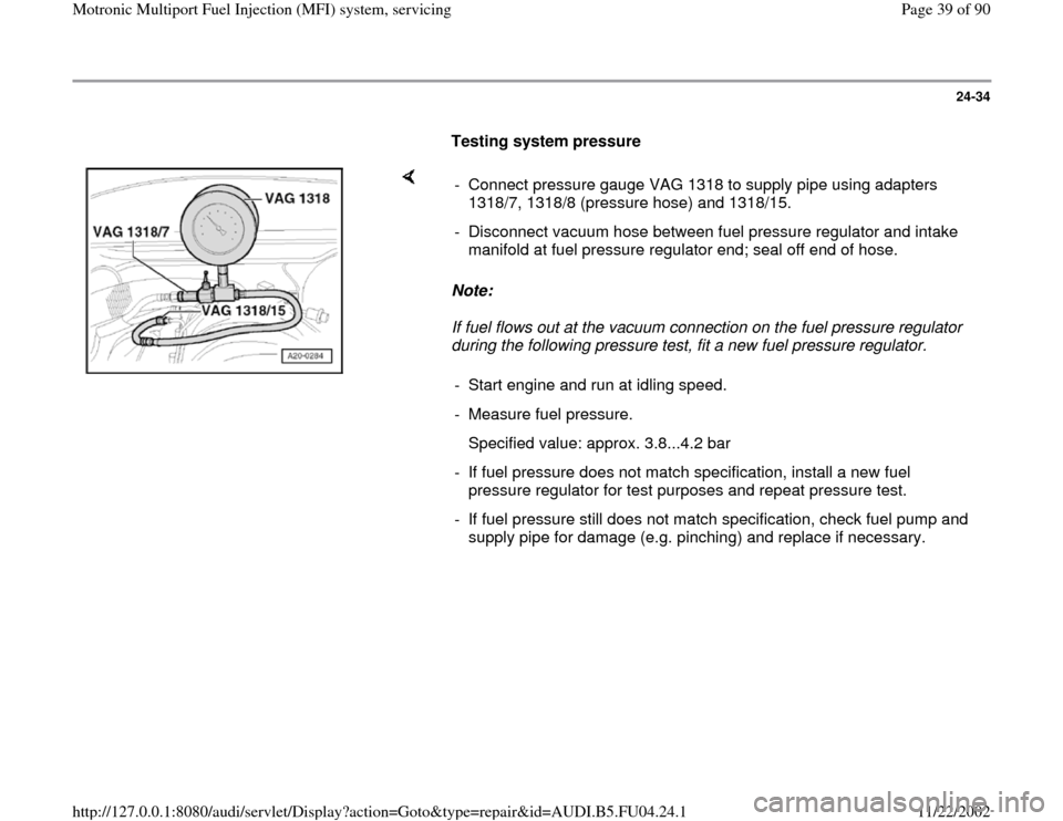
Testing system pressure
Note:
If fuel flows out at the vacuum connection on the fuel pressure regulator
during the following pressure test, fit a new fuel pressure regulator. - Connect pressure gauge VAG 1318 to supply pipe using adapters
1318/7, 1318/8 (pressure hose) and 1318/15.
- Disconnect vacuum hose between fuel pressure regulator and intake
manifold at fuel pressure regulator end; seal off end of hose.
- Start engine and run at idling speed.
- Measure fuel pressure.
Specified value: approx. 3.8...4.2 bar
- If fuel pressure does not match specification, install a new fuel
pressure regulator for test purposes and repeat pressure test.
- If fuel pressure still does not match specification, check fuel pump and
supply pipe for damage (e.g. pinching) and replace if necessary.
Pa
ge 39 of 90 Motronic Multi
port Fuel In
jection
(MFI
) system, servicin
g
11/22/2002 htt
p://127.0.0.1:8080/audi/servlet/Dis
play?action=Goto&t
yp
e=re
pair&id=AUDI.B5.FU04.24.1
Page 43 of 90
24-37
Note:
A rise in pressure (due to fuel expansion) when
the engine is at operating temperature is normal.
- Start the engine and run at idling speed.
- Switch ignition off after the pressure has built-
up. At the same time close pressure gauge cut-
off tap (lever at 90 to through flow direction). If the pressure does not drop, the following faults
are possible:
Union between pressure gauge and fuel supply
pipe leaking
Supply pipe leaking at fuel tank
Return valve in fuel pump leaking
Repair Manual, Fuel Supply System, Repair
Group 20
Note:
When the cut-off tap is closed the pressure
gauge will indicate the pressure downstream of
Pa
ge 43 of 90 Motronic Multi
port Fuel In
jection
(MFI
) system, servicin
g
11/22/2002 htt
p://127.0.0.1:8080/audi/servlet/Dis
play?action=Goto&t
yp
e=re
pair&id=AUDI.B5.FU04.24.1
Page 57 of 90
24-48
Checking for leaks
- Bridge sockets 1 and 65 on the test box using
test leads from VAG1594 A connector test kit.
(This creates an Ground (GND) connection to
one side of the fuel pump relay coil.)
Note:
Once the socket are bridged the fuel pump runs
continuously, even if the engine is not running.
This is because the fuel pump relay receives its
positive voltage supply via the central electrics.
The negative voltage supply for the fuel pump
relay comes via the cable bridge on the test box.
WARNING!
Fire hazard. DO NOT smoke or work near
heaters or have anything in the area that can
ignite fuel!
- Check injectors fuel for leaks (visual check).
When fuel pump is running, only 1 or 2 drops
should escape per minute from each injector.
- If fuel loss is greater, switch off fuel pump
(remove bridge) and replace faulty injector
Page 24
-53
, also observe notes on Page 24
-
53
.
Pa
ge 57 of 90 Motronic Multi
port Fuel In
jection
(MFI
) system, servicin
g
11/22/2002 htt
p://127.0.0.1:8080/audi/servlet/Dis
play?action=Goto&t
yp
e=re
pair&id=AUDI.B5.FU04.24.1
Page 59 of 90
24-49
WARNING!
Make sure test box is inside of passenger compartment.
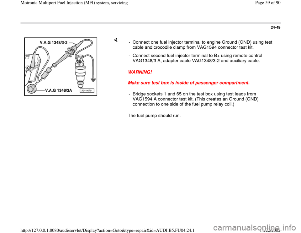
The fuel pump should run. - Connect one fuel injector terminal to engine Ground (GND) using test
cable and crocodile clamp from VAG1594 connector test kit.
- Connect second fuel injector terminal to B+ using remote control
VAG1348/3 A, adapter cable VAG1348/3-2 and auxiliary cable.
- Bridge sockets 1 and 65 on the test box using test leads from
VAG1594 A connector test kit. (This creates an Ground (GND)
connection to one side of the fuel pump relay coil.)
Pa
ge 59 of 90 Motronic Multi
port Fuel In
jection
(MFI
) system, servicin
g
11/22/2002 htt
p://127.0.0.1:8080/audi/servlet/Dis
play?action=Goto&t
yp
e=re
pair&id=AUDI.B5.FU04.24.1