low AUDI A4 1998 B5 / 1.G ATW Engine Motronic Fuel Injection Syst
[x] Cancel search | Manufacturer: AUDI, Model Year: 1998, Model line: A4, Model: AUDI A4 1998 B5 / 1.GPages: 81, PDF Size: 1.03 MB
Page 1 of 81
24-1
Motronic fuel injection
system, servicing
Safety precautions
If special testing equipment is required during
road test, note the following:
WARNING!
Test equipment must always be secured to
the rear seat and operated from there by a
second person.
If test and measuring equipment is operated
from the passenger seat, the person seated
there could be injured in the event of an
accident involving deployment of the
passenger-side airbag.
To reduce the risk of personal injury and/or
damage to the fuel injection and ignition system,
always observe the following:
Only disconnect and reconnect wires for
injection and ignition system, including test
leads, when ignition is turned off.
If engine is to be cranked at starting RPM
without starting (e.g. for compression testing),
Pa
ge 1 of 81 Motronic fuel in
jection s
ystem, servicin
g
11/21/2002 htt
p://127.0.0.1:8080/audi/servlet/Dis
play?action=Goto&t
yp
e=re
pair&id=AUDI.B5.FU06.24.1
Page 4 of 81
24-3
Rules of cleanliness
When working on the fuel supply or fuel injection
systems, the following "6 rules of cleanliness"
should be carefully observed:
Thoroughly clean all connections and the
surrounding area before disconnecting.
Place parts that have been removed on a clean
surface and cover. Use lint-free cloths only!
Carefully cover over opened components or
seal, if repairs are not carried out immediately.
Only install clean components:Only unpack
replacement parts immediately prior to
installation. Do not use parts that have been
stored loose (in tool boxes etc.)
When the system is open:Do not work with
compressed air if it can be avoided. Do not
move vehicle unless absolutely necessary.
Disconnected electrical harness
connectors:Protect from dirt and moisture. Be
sure harness connector is dry before
connecting.
Pa
ge 4 of 81 Motronic fuel in
jection s
ystem, servicin
g
11/21/2002 htt
p://127.0.0.1:8080/audi/servlet/Dis
play?action=Goto&t
yp
e=re
pair&id=AUDI.B5.FU06.24.1
Page 10 of 81
24-9
Repair Manual, 1.8 Liter 4
-Cyl. 5V Turbo Engine
Mechanical, Engine Code(s): AEB, ATW, Repair Group 26; Secondary Air Injection (AIR) system, checking
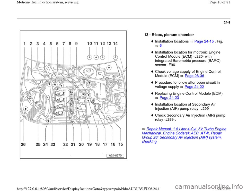
13 -
E-box, plenum chamber Installation locations Page 24
-15
, Fig.
6
Installation location for motronic Engine
Control Module (ECM) -J220- with
integrated Barometric pressure (BARO)
sensor -F96- Check voltage supply of Engine Control
Module (ECM) Page 28
-36
Procedure to follow after open circuit in
voltage supply Page 24
-22
Replacing Engine Control Module (ECM)
Page 24
-23
Installation location of Secondary Air
Injection (AIR) pump relay -J299- Check Secondary Air Injection (AIR) pump
relay -J299-:
Pa
ge 10 of 81 Motronic fuel in
jection s
ystem, servicin
g
11/21/2002 htt
p://127.0.0.1:8080/audi/servlet/Dis
play?action=Goto&t
yp
e=re
pair&id=AUDI.B5.FU06.24.1
Page 13 of 81
24-12
Repair Manual, 1.8 Liter 4
-Cyl. 5V Turbo Engine
Mechanical, Engine Code(s): AEB, ATW, Repair Group 21, Charge air system with turbocharger, checking
Repair Manual, 1.8 Liter 4
-Cyl. 5V Turbo Engine
Mechanical, Engine Code(s): AEB, ATW, Repair Group 26; Secondary Air Injection (AIR) system, checking
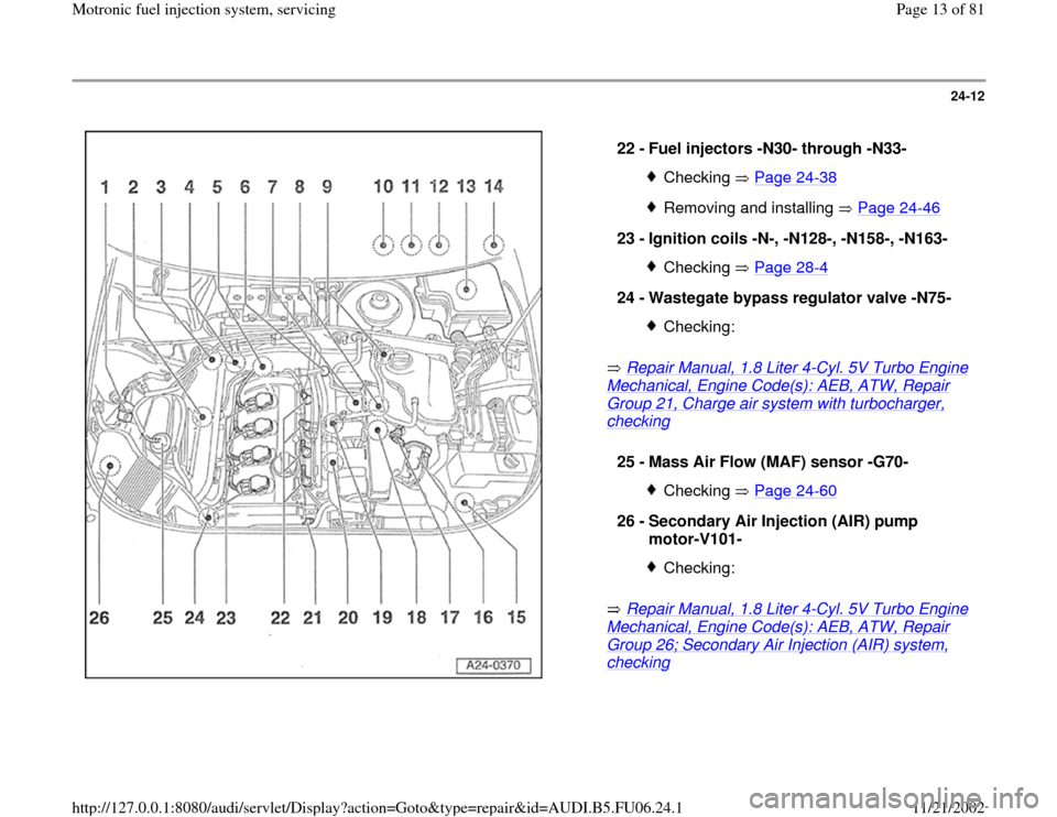
22 -
Fuel injectors -N30- through -N33- Checking Page 24
-38
Removing and installing Page 24
-46
23 -
Ignition coils -N-, -N128-, -N158-, -N163-
Checking Page 28
-4
24 -
Wastegate bypass regulator valve -N75-
Checking:
25 -
Mass Air Flow (MAF) sensor -G70-
Checking Page 24
-60
26 -
Secondary Air Injection (AIR) pump
motor-V101-
Checking:
Pa
ge 13 of 81 Motronic fuel in
jection s
ystem, servicin
g
11/21/2002 htt
p://127.0.0.1:8080/audi/servlet/Dis
play?action=Goto&t
yp
e=re
pair&id=AUDI.B5.FU06.24.1
Page 14 of 81
24-13
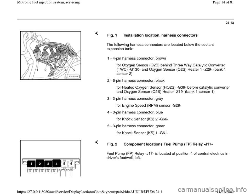
The following harness connectors are located below the coolant
expansion tank: Fig. 1 Installation location, harness connectors
1 - 4-pin harness connector, brown
for Oxygen Sensor (O2S) behind Three Way Catalytic Converter
(TWC) -G130- and Oxygen Sensor (O2S) Heater 1 -Z29- (bank 1
sensor 2)
2 - 6-pin harness connector, black
for Heated Oxygen Sensor (HO2S) -G39- before catalytic converter
and Oxygen Sensor (O2S) Heater -Z19- (bank 1 sensor 1)
3 - 3-pin harness connector, gray
for Engine Speed (RPM) sensor -G28-
4 - 3-pin harness connector, blue
for Knock Sensor (KS) 2 -G66-
5 - 3-pin harness connector, green
for Knock Sensor (KS) 1 -G61-
Fuel Pump (FP) Relay -J17- is located at position 4 of central electrics in
driver's footwell, left. Fig. 2 Component locations Fuel Pump (FP) Relay -J17-
Pa
ge 14 of 81 Motronic fuel in
jection s
ystem, servicin
g
11/21/2002 htt
p://127.0.0.1:8080/audi/servlet/Dis
play?action=Goto&t
yp
e=re
pair&id=AUDI.B5.FU06.24.1
Page 15 of 81
24-14
Note:
In order to assure sufficiently secure fitting, switches must not be installed
more than once.
Adjusting switch:
Repair Manual, Brake System, Repair Group 46, Brake booster, removing and installing
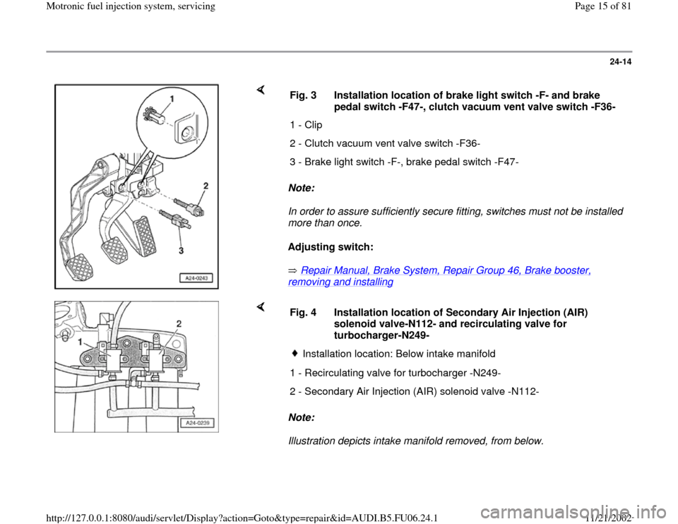
Fig. 3 Installation location of brake light switch -F- and brake
pedal switch -F47-, clutch vacuum vent valve switch -F36-
1 - Clip
2 - Clutch vacuum vent valve switch -F36-
3 - Brake light switch -F-, brake pedal switch -F47-
Note:
Illustration depicts intake manifold removed, from below. Fig. 4 Installation location of Secondary Air Injection (AIR)
solenoid valve-N112- and recirculating valve for
turbocharger-N249-
Installation location: Below intake manifold
1 - Recirculating valve for turbocharger -N249-
2 - Secondary Air Injection (AIR) solenoid valve -N112-
Pa
ge 15 of 81 Motronic fuel in
jection s
ystem, servicin
g
11/21/2002 htt
p://127.0.0.1:8080/audi/servlet/Dis
play?action=Goto&t
yp
e=re
pair&id=AUDI.B5.FU06.24.1
Page 18 of 81

24-17
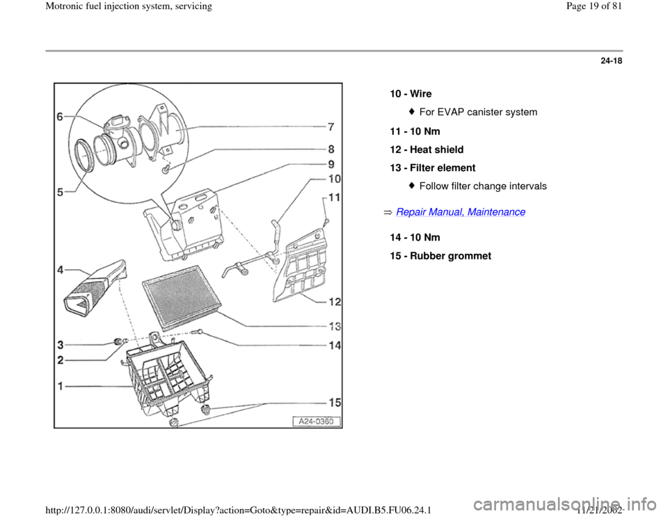
Air cleaner, disassembling and
assembling
1 -
Lower part of air cleaner housing
2 -
Sleeve
3 -
Rubber grommet
4 -
Air duct
to metering unit
5 -
Seal
6 -
Mass Air Flow (MAF) sensor -G70- Checking Page 24
-60
7 -
Air duct
8 -
6 Nm
9 -
Upper part of air cleaner housing
Pa
ge 18 of 81 Motronic fuel in
jection s
ystem, servicin
g
11/21/2002 htt
p://127.0.0.1:8080/audi/servlet/Dis
play?action=Goto&t
yp
e=re
pair&id=AUDI.B5.FU06.24.1
Page 19 of 81
24-18
Repair Manual, Maintenance
10 -
Wire
For EVAP canister system
11 -
10 Nm
12 -
Heat shield
13 -
Filter element Follow filter change intervals
14 -
10 Nm
15 -
Rubber grommet
Pa
ge 19 of 81 Motronic fuel in
jection s
ystem, servicin
g
11/21/2002 htt
p://127.0.0.1:8080/audi/servlet/Dis
play?action=Goto&t
yp
e=re
pair&id=AUDI.B5.FU06.24.1
Page 22 of 81
24-21
Note:
Important note:
After re-connecting the Engine Control Module
(ECM), the following work steps must be
performed:
- Perform adaptation of the Throttle Valve Control
Module -J338- Page 24
-121
.
- For vehicles with automatic transmission, the
kick down function must be adapted Page 24
-
139
.
- Check DTC memory and erase it if necessary
Page 01
-16
.
- If DTC memory was erased, readiness code
must be re-generated Page 01
-73
.
Note:
During the first adaptation phase, it is possible
that idle will be rough and vehicle may shake
lightly in drive mode.
Pa
ge 22 of 81 Motronic fuel in
jection s
ystem, servicin
g
11/21/2002 htt
p://127.0.0.1:8080/audi/servlet/Dis
play?action=Goto&t
yp
e=re
pair&id=AUDI.B5.FU06.24.1
Page 23 of 81
24-22
Procedure following interruption of
voltage supply
Note:
Important note:
After re-connecting voltage supply, the following
work steps must be performed:
- Perform adaptation of the Throttle Valve Control
Module -J338- Page 24
-121
.
- For vehicles with automatic transmission, the
kick down function must be adapted Page 24
-
139
.
- Check DTC memory and erase it if necessary
Page 01
-16
.
- If DTC memory was erased, readiness code
must be re-generated Page 01
-73
.
Note:
During the first adaptation phase, it is possible
that idle will be rough and vehicle may shake
lightly in drive mode.
Pa
ge 23 of 81 Motronic fuel in
jection s
ystem, servicin
g
11/21/2002 htt
p://127.0.0.1:8080/audi/servlet/Dis
play?action=Goto&t
yp
e=re
pair&id=AUDI.B5.FU06.24.1