ABS AUDI A4 1998 B5 / 1.G Brakes Erase DTC Memory End Output Workshop Manual
[x] Cancel search | Manufacturer: AUDI, Model Year: 1998, Model line: A4, Model: AUDI A4 1998 B5 / 1.GPages: 15, PDF Size: 0.09 MB
Page 2 of 15
01-12
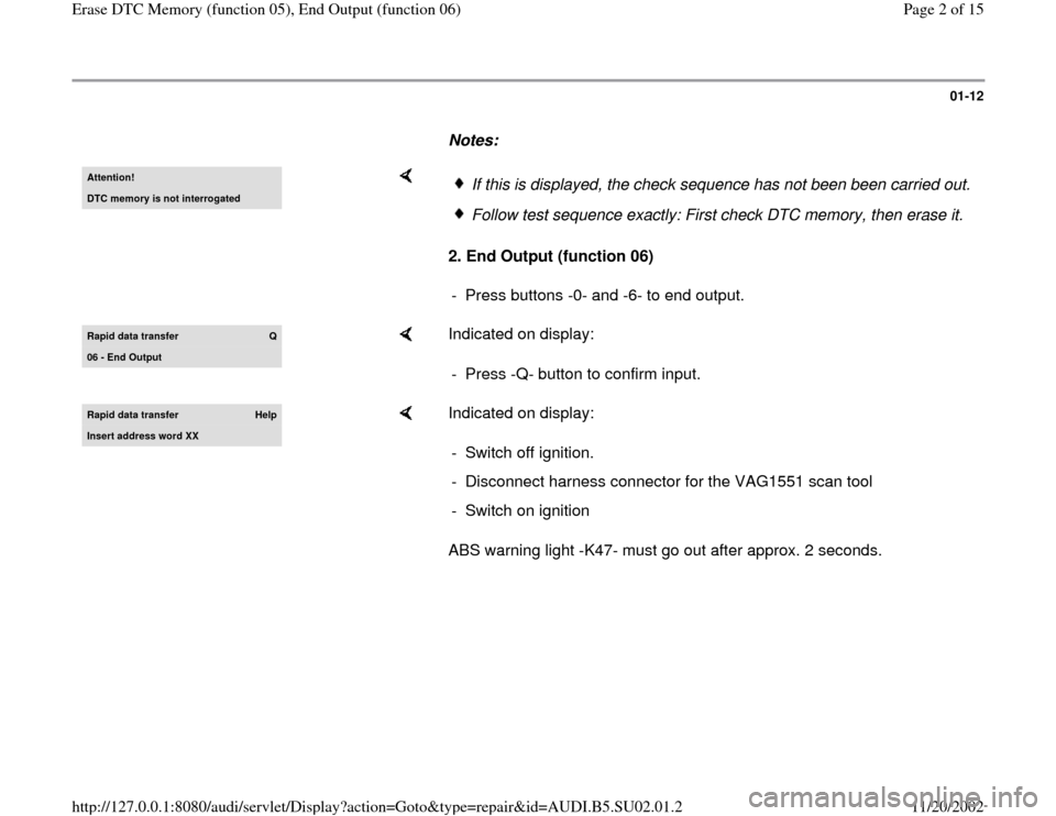
Notes: Attention!DTC memory is not interrogated
2. End Output (function 06)
If this is displayed, the check sequence has not been been carried out.Follow test sequence exactly: First check DTC memory, then erase it.
- Press buttons -0- and -6- to end output.
Rapid data transfer
Q
06 - End Output
Indicated on display:
- Press -Q- button to confirm input.
Rapid data transfer
Help
Insert address word XX
Indicated on display:
ABS warning light -K47- must go out after approx. 2 seconds. - Switch off ignition.
- Disconnect harness connector for the VAG1551 scan tool
- Switch on ignition
Pa
ge 2 of 15 Erase DTC Memor
y (function 05
), End Out
put
(function 06
)
11/20/2002 htt
p://127.0.0.1:8080/audi/servlet/Dis
play?action=Goto&t
yp
e=re
pair&id=AUDI.B5.SU02.01.2
Page 7 of 15
01-17
Safety precautions and troubleshooting
basics
ABS/EDL/ASR and ESP are vehicle safety
systems; working on these systems requires
specific system knowledge.
There are two different versions of instrument
cluster: with or without Driver Information
System (DIS).
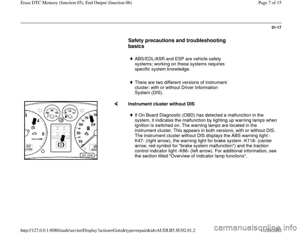
Instrument cluster without DIS
If On Board Diagnostic (OBD) has detected a malfunction in the
system, it indicates the malfunction by lighting up warning lamps when
ignition is switched on. The warning lamps are located in the
instrument cluster. This appears in both versions, with or without DIS.
The instrument cluster without DIS displays the ABS warning light -
K47- (right arrow), the warning light for brake system -K118- (center
arrow, red symbol for "brake system malfunction") and the traction
control indicator light -K86- (left arrow). For additional information, see
the section titled "Overview of indicator lamp functions".
Pa
ge 7 of 15 Erase DTC Memor
y (function 05
), End Out
put
(function 06
)
11/20/2002 htt
p://127.0.0.1:8080/audi/servlet/Dis
play?action=Goto&t
yp
e=re
pair&id=AUDI.B5.SU02.01.2
Page 8 of 15
01-18
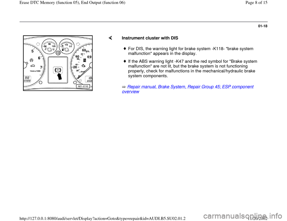
Instrument cluster with DIS
Repair manual, Brake System, Repair Group 45; ESP component overview
For DIS, the warning light for brake system -K118- "brake system
malfunction" appears in the display. If the ABS warning light -K47 and the red symbol for "Brake system
malfunction" are not lit, but the brake system is not functioning
properly, check for malfunctions in the mechanical/hydraulic brake
system components.
Pa
ge 8 of 15 Erase DTC Memor
y (function 05
), End Out
put
(function 06
)
11/20/2002 htt
p://127.0.0.1:8080/audi/servlet/Dis
play?action=Goto&t
yp
e=re
pair&id=AUDI.B5.SU02.01.2
Page 11 of 15
01-21
Only replace a malfunctioning component if you
are certain that all electrical wires to this
component are functioning properly. The lines
must work properly and be capable of carrying
all signals without any problems. Check the
lines for the following:
- Corrosion or loose connections in the
connectors or Ground straps. If there are bent,
broken, or corroded contacts on the
connectors, replace the contacts using
VAS1978 wiring harness repair kit.
- Open circuit in wiring
- Short circuits to B+ or Ground (GND)
Electrical Wiring Diagrams, Troubleshooting &
Component Locations
Welding work performed with electrical welding
equipment can affect the ABS/ESP system.
Pa
ge 11 of 15 Erase DTC Memor
y (function 05
), End Out
put
(function 06
)
11/20/2002 htt
p://127.0.0.1:8080/audi/servlet/Dis
play?action=Goto&t
yp
e=re
pair&id=AUDI.B5.SU02.01.2
Page 12 of 15
01-22
Test requirements
Vehicle equipped with approved wheel and
tire sizes, which must be the same on all four
wheels. All tire inflation pressures checked
according to specification.
The mechanical/hydraulic components of the
brake system are OK. Hydraulic connections
and lines are sealed properly (visual check
at hydraulic unit, brake calipers, wheel
cylinders, tandem master brake cylinder).
Wheel bearings and wheel bearing play OK
Wheel speed sensors installed correctly
Repair manual, Brake System, Repair Group
45
Supply voltage OK (at least 10.0 volts).
Harness connector is properly connected at
ABS control module -J104-, locking
mechanism is engaged.
Pa
ge 12 of 15 Erase DTC Memor
y (function 05
), End Out
put
(function 06
)
11/20/2002 htt
p://127.0.0.1:8080/audi/servlet/Dis
play?action=Goto&t
yp
e=re
pair&id=AUDI.B5.SU02.01.2