ignition AUDI A4 1998 B5 / 1.G Brakes Output DTM 03 Workshop Manual
[x] Cancel search | Manufacturer: AUDI, Model Year: 1998, Model line: A4, Model: AUDI A4 1998 B5 / 1.GPages: 66, PDF Size: 0.34 MB
Page 20 of 66
01-166
Electrical testing
If the On Board Diagnostic (OBD) sequence
does not provide any indication of the source of
the malfunction, work through all of the
electrical test steps.
If the OBD sequence identifies the source of the
malfunction, only carry out the test steps
recommended in the DTC table (specific
testing).
Test requirements
The "Automatic Test Sequence" was carried
out and it was determined that the
Transmission Control Module (TCM) and
Engine Control Module (ECM) only contain
DTCs relating to ABS/EDL.
- Connect the VAG1551 Scan Tool (ST) and
select the address word 00 with ignition
switched on;
- After completing electrical test, check and
erase DTC memories of Transmission Control
Module (TCM) and Engine Control Module
(ECM).
Pa
ge 20 of 66 Out
put Dia
gnostic Test Mode
(DTM
) (function 03
)
11/20/2002 htt
p://127.0.0.1:8080/audi/servlet/Dis
play?action=Goto&t
yp
e=re
pair&id=AUDI.B5.SU02.01.13
Page 21 of 66
01-167
Note:
The operation manual for the VAS1978 wiring harness repair kit generally
forbids the repair of any lines in the ABS or related systems. This rule only
pertains to the shielded lines in these systems.
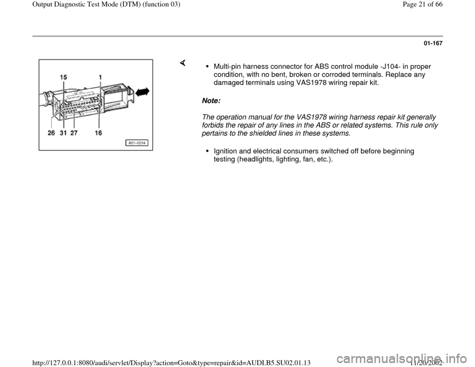
Multi-pin harness connector for ABS control module -J104- in proper
condition, with no bent, broken or corroded terminals. Replace any
damaged terminals using VAS1978 wiring repair kit. Ignition and electrical consumers switched off before beginning
testing (headlights, lighting, fan, etc.).
Pa
ge 21 of 66 Out
put Dia
gnostic Test Mode
(DTM
) (function 03
)
11/20/2002 htt
p://127.0.0.1:8080/audi/servlet/Dis
play?action=Goto&t
yp
e=re
pair&id=AUDI.B5.SU02.01.13
Page 23 of 66
01-169
Connect VAG1598 test box using VAG1598/27
adapter.
- Switch ignition off.
- Connect VAG1598/27 adapter and VAG1598
test box. Disconnect multi-pin connector from
ABS control module -J104-. Connect
VAG1598/27 adapter and VAG1598 test box to
connector of ABS/EDL wiring harness.
The socket designations on the VAG1598 test
box are identical to the terminal designations on
the ABS control module -J104- and on the wiring
harness connector.
Electrical Wiring Diagrams, Troubleshooting &
Component Locations
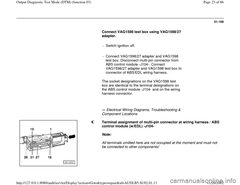
Terminal assignment of multi-pin connector at wiring harness / ABS
control module (w/EDL) -J104-
Note:
All terminals omitted here are not occupied at the moment and must not
be connected to other components!
Pa
ge 23 of 66 Out
put Dia
gnostic Test Mode
(DTM
) (function 03
)
11/20/2002 htt
p://127.0.0.1:8080/audi/servlet/Dis
play?action=Goto&t
yp
e=re
pair&id=AUDI.B5.SU02.01.13
Page 29 of 66
01-174
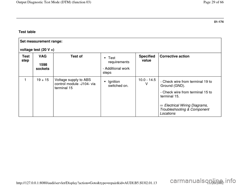
Test table Set measurement range:
voltage test (20 V =)
Test
step VAG
1598
sockets Test of
Test
requirements
- Additional work
steps Specified
value Corrective action
1 19 + 15 Voltage supply to ABS
control module -J104- via
terminal 15 Ignition
switched on. 10.0 - 14.5
V
Electrical Wiring Diagrams,
Troubleshooting & Component
Locations - Check wire from terminal 19 to
Ground (GND).
- Check wire from terminal 15 to
terminal 15.
Pa
ge 29 of 66 Out
put Dia
gnostic Test Mode
(DTM
) (function 03
)
11/20/2002 htt
p://127.0.0.1:8080/audi/servlet/Dis
play?action=Goto&t
yp
e=re
pair&id=AUDI.B5.SU02.01.13
Page 30 of 66
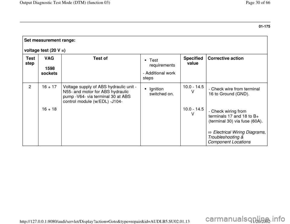
01-175
Set measurement range:
voltage test (20 V =)
Test
step VAG
1598
sockets Test of
Test
requirements
- Additional work
steps Specified
value Corrective action
2 16 + 17 Voltage supply of ABS hydraulic unit -
N55- and motor for ABS hydraulic
pump -V64- via terminal 30 at ABS
control module (w/EDL) -J104- Ignition
switched on. 10.0 - 14.5
V - Check wire from terminal
16 to Ground (GND).
16 + 18 10.0 - 14.5
V
Electrical Wiring Diagrams,
Troubleshooting &
Component Locations - Check wiring from
terminals 17 and 18 to B+
(terminal 30) via fuse (60A).
Pa
ge 30 of 66 Out
put Dia
gnostic Test Mode
(DTM
) (function 03
)
11/20/2002 htt
p://127.0.0.1:8080/audi/servlet/Dis
play?action=Goto&t
yp
e=re
pair&id=AUDI.B5.SU02.01.13
Page 31 of 66
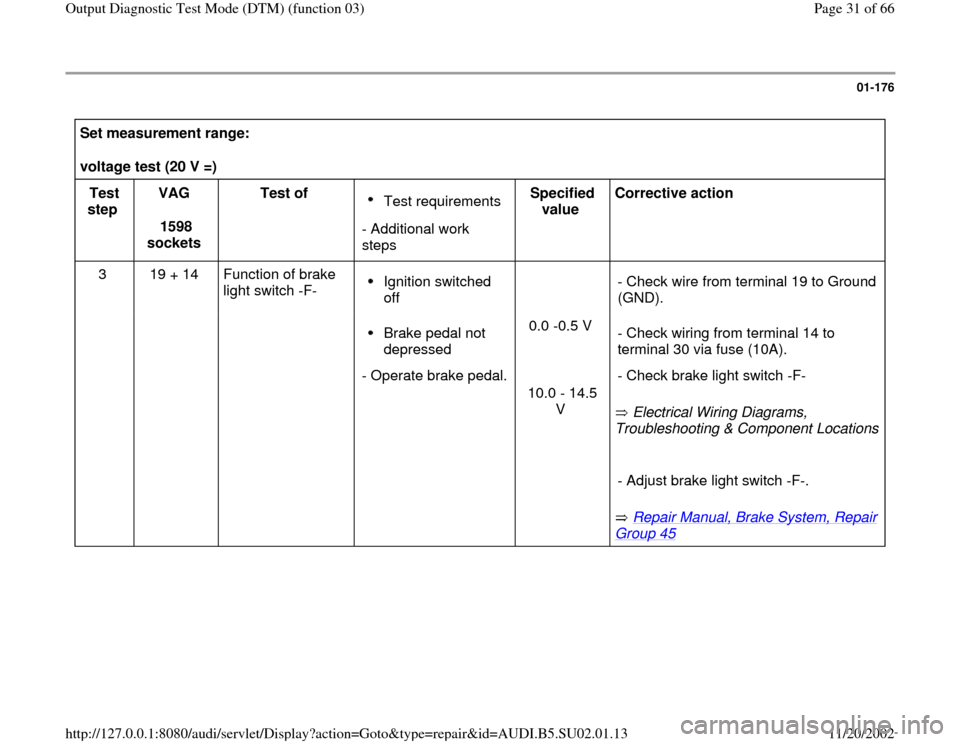
01-176
Set measurement range:
voltage test (20 V =)
Test
step VAG
1598
sockets Test of
Test requirements
- Additional work
steps Specified
value Corrective action
3 19 + 14 Function of brake
light switch -F- Ignition switched
off
- Check wire from terminal 19 to Ground
(GND).
Brake pedal not
depressed
- Operate brake pedal.0.0 -0.5 V
10.0 - 14.5
V
Electrical Wiring Diagrams,
Troubleshooting & Component Locations
Repair Manual, Brake System, Repair
Group 45
- Check wiring from terminal 14 to
terminal 30 via fuse (10A).
- Check brake light switch -F-
- Adjust brake light switch -F-.
Pa
ge 31 of 66 Out
put Dia
gnostic Test Mode
(DTM
) (function 03
)
11/20/2002 htt
p://127.0.0.1:8080/audi/servlet/Dis
play?action=Goto&t
yp
e=re
pair&id=AUDI.B5.SU02.01.13
Page 32 of 66
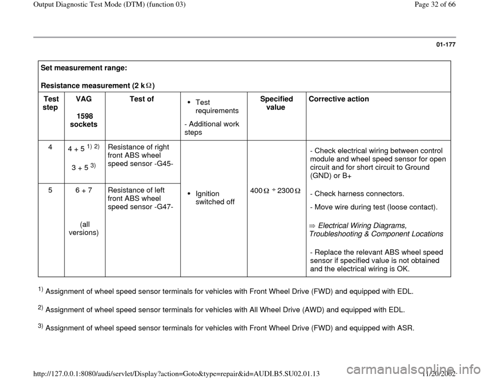
01-177
Set measurement range:
Resistance measurement (2 k ) Test
step VAG
1598
sockets Test of
Test
requirements
- Additional work
steps Specified
value Corrective action
4
4 + 5
1) 2)
3 + 5
3) Resistance of right
front ABS wheel
speed sensor -G45-
- Check electrical wiring between control
module and wheel speed sensor for open
circuit and for short circuit to Ground
(GND) or B+
5 6 + 7
(all
versions) Resistance of left
front ABS wheel
speed sensor -G47-
Ignition
switched off 400 2300
Electrical Wiring Diagrams,
Troubleshooting & Component Locations - Check harness connectors.
- Move wire during test (loose contact).- Replace the relevant ABS wheel speed
sensor if specified value is not obtained
and the electrical wiring is OK.
1) Assignment of wheel speed sensor terminals for vehicles with Front Wheel Drive (FWD) and equipped with EDL. 2) Assignment of wheel speed sensor terminals for vehicles with All Wheel Drive (AWD) and equipped with EDL. 3) Assignment of wheel speed sensor terminals for vehicles with Front Wheel Drive (FWD) and equipped with ASR.
Pa
ge 32 of 66 Out
put Dia
gnostic Test Mode
(DTM
) (function 03
)
11/20/2002 htt
p://127.0.0.1:8080/audi/servlet/Dis
play?action=Goto&t
yp
e=re
pair&id=AUDI.B5.SU02.01.13
Page 33 of 66
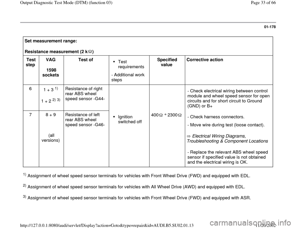
01-178
Set measurement range:
Resistance measurement (2 k ) Test
step VAG
1598
sockets Test of
Test
requirements
- Additional work
steps Specified
value Corrective action
6
1 + 3
1)
1 + 2
2) 3) Resistance of right
rear ABS wheel
speed sensor -G44-
- Check electrical wiring between control
module and wheel speed sensor for open
circuits and for short circuit to Ground
(GND) or B+
7 8 + 9
(all
versions) Resistance of left
rear ABS wheel
speed sensor -G46-
Ignition
switched off 400 2300
Electrical Wiring Diagrams,
Troubleshooting & Component Locations - Check harness connectors.
- Move wire during test (loose contact).- Replace the relevant ABS wheel speed
sensor if specified value is not obtained
and the electrical wiring is OK.
1) Assignment of wheel speed sensor terminals for vehicles with Front Wheel Drive (FWD) and equipped with EDL. 2) Assignment of wheel speed sensor terminals for vehicles with All Wheel Drive (AWD) and equipped with EDL. 3) Assignment of wheel speed sensor terminals for vehicles with Front Wheel Drive (FWD) and equipped with ASR.
Pa
ge 33 of 66 Out
put Dia
gnostic Test Mode
(DTM
) (function 03
)
11/20/2002 htt
p://127.0.0.1:8080/audi/servlet/Dis
play?action=Goto&t
yp
e=re
pair&id=AUDI.B5.SU02.01.13
Page 34 of 66
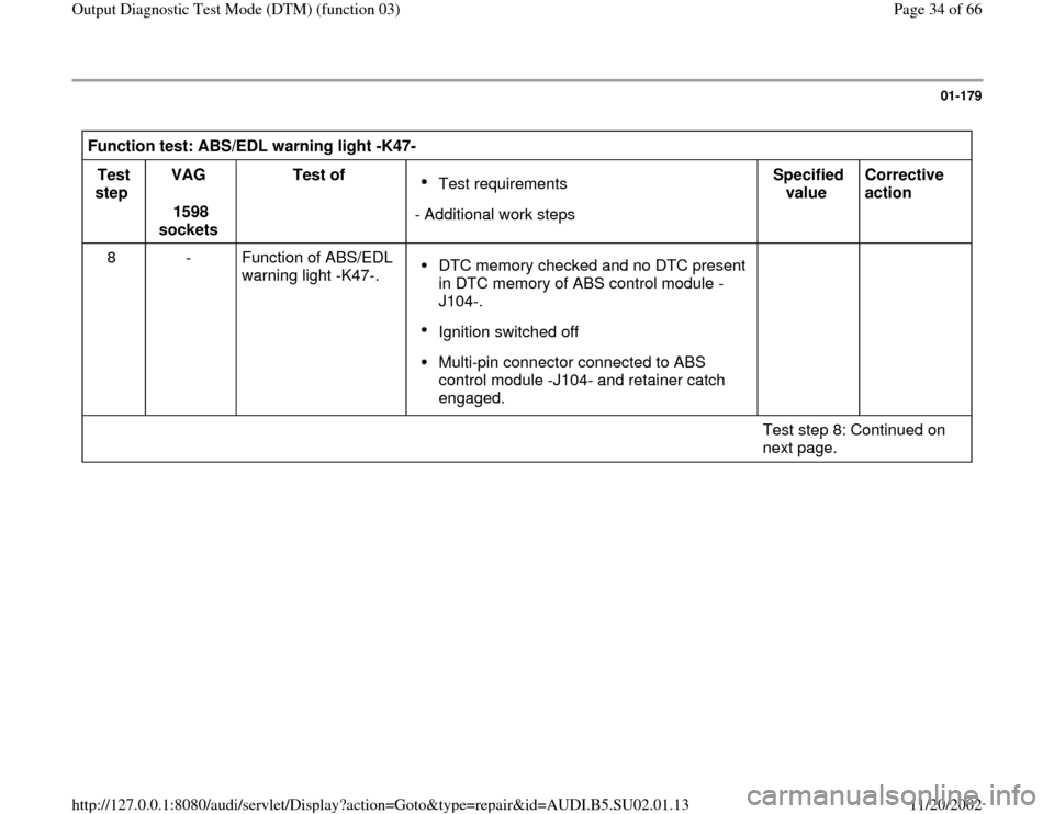
01-179
Function test: ABS/EDL warning light -K47-
Test
step VAG
1598
sockets Test of
Test requirements
- Additional work stepsSpecified
value Corrective
action
8 - Function of ABS/EDL
warning light -K47-. DTC memory checked and no DTC present
in DTC memory of ABS control module -
J104-. Ignition switched off Multi-pin connector connected to ABS
control module -J104- and retainer catch
engaged.
Test step 8: Continued on
next page.
Pa
ge 34 of 66 Out
put Dia
gnostic Test Mode
(DTM
) (function 03
)
11/20/2002 htt
p://127.0.0.1:8080/audi/servlet/Dis
play?action=Goto&t
yp
e=re
pair&id=AUDI.B5.SU02.01.13
Page 35 of 66
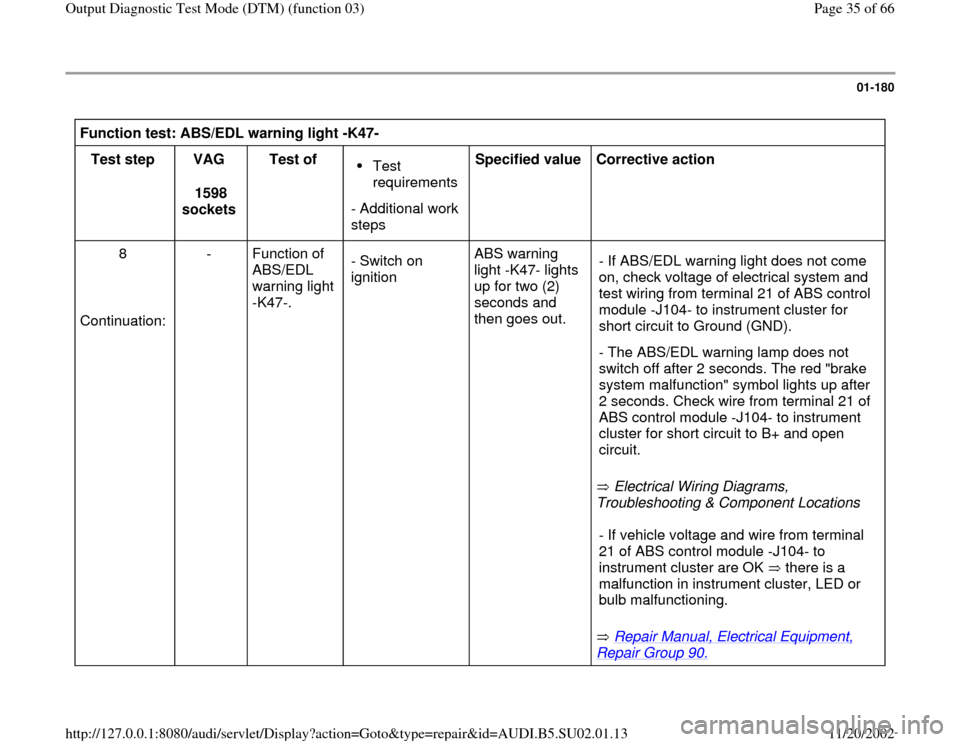
01-180
Function test: ABS/EDL warning light -K47-
Test step
VAG
1598
sockets Test of
Test
requirements
- Additional work
steps Specified value
Corrective action
8
Continuation: - Function of
ABS/EDL
warning light
-K47-. - Switch on
ignition ABS warning
light -K47- lights
up for two (2)
seconds and
then goes out.
Electrical Wiring Diagrams,
Troubleshooting & Component Locations - If ABS/EDL warning light does not come
on, check voltage of electrical system and
test wiring from terminal 21 of ABS control
module -J104- to instrument cluster for
short circuit to Ground (GND).
- The ABS/EDL warning lamp does not
switch off after 2 seconds. The red "brake
system malfunction" symbol lights up after
2 seconds. Check wire from terminal 21 of
ABS control module -J104- to instrument
cluster for short circuit to B+ and open
circuit.
Repair Manual, Electrical Equipment,
Repair Group 90.
- If vehicle voltage and wire from terminal
21 of ABS control module -J104- to
instrument cluster are OK there is a
malfunction in instrument cluster, LED or
bulb malfunctioning.
Pa
ge 35 of 66 Out
put Dia
gnostic Test Mode
(DTM
) (function 03
)
11/20/2002 htt
p://127.0.0.1:8080/audi/servlet/Dis
play?action=Goto&t
yp
e=re
pair&id=AUDI.B5.SU02.01.13