RADIO CLOCK AUDI A4 1998 B5 / 1.G Radio System Workshop Manual
[x] Cancel search | Manufacturer: AUDI, Model Year: 1998, Model line: A4, Model: AUDI A4 1998 B5 / 1.GPages: 45, PDF Size: 0.52 MB
Page 1 of 45
91-1
Radio systems
General information
CAUTION!
Before working on the electrical system:
Determine the correct coding for the anti-
theft radio.
Disconnect the battery Ground (GND)
strap.
Note:
After re-connecting the battery, activate the
vehicle's electrical equipment (radio, clock,
power windows, engine) according to the owner's
manual.
Pa
ge 1 of 45 Radio s
ystems
11/20/2002 htt
p://127.0.0.1:8080/audi/servlet/Dis
play?action=Goto&t
yp
e=re
pair&id=AUDI.B5.EE02.91.1
Page 7 of 45
91-5
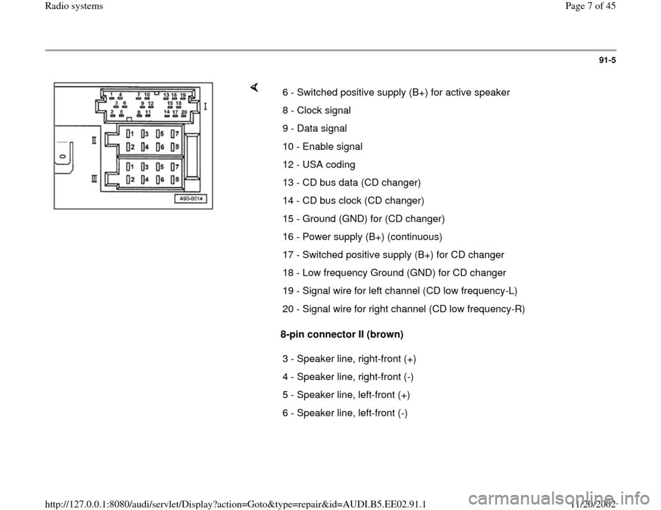
8-pin connector II (brown) 6 - Switched positive supply (B+) for active speaker
8 - Clock signal
9 - Data signal
10 - Enable signal
12 - USA coding
13 - CD bus data (CD changer)
14 - CD bus clock (CD changer)
15 - Ground (GND) for (CD changer)
16 - Power supply (B+) (continuous)
17 - Switched positive supply (B+) for CD changer
18 - Low frequency Ground (GND) for CD changer
19 - Signal wire for left channel (CD low frequency-L)
20 - Signal wire for right channel (CD low frequency-R)
3 - Speaker line, right-front (+)
4 - Speaker line, right-front (-)
5 - Speaker line, left-front (+)
6 - Speaker line, left-front (-)
Pa
ge 7 of 45 Radio s
ystems
11/20/2002 htt
p://127.0.0.1:8080/audi/servlet/Dis
play?action=Goto&t
yp
e=re
pair&id=AUDI.B5.EE02.91.1
Page 10 of 45
91-8
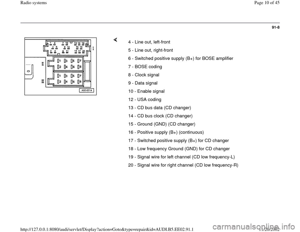
4 - Line out, left-front
5 - Line out, right-front
6 - Switched positive supply (B+) for BOSE amplifier
7 - BOSE coding
8 - Clock signal
9 - Data signal
10 - Enable signal
12 - USA coding
13 - CD bus data (CD changer)
14 - CD bus clock (CD changer)
15 - Ground (GND) (CD changer)
16 - Positive supply (B+) (continuous)
17 - Switched positive supply (B+) for CD changer
18 - Low frequency Ground (GND) for CD changer
19 - Signal wire for left channel (CD low frequency-L)
20 - Signal wire for right channel (CD low frequency-R)
Pa
ge 10 of 45 Radio s
ystems
11/20/2002 htt
p://127.0.0.1:8080/audi/servlet/Dis
play?action=Goto&t
yp
e=re
pair&id=AUDI.B5.EE02.91.1
Page 13 of 45
91-11
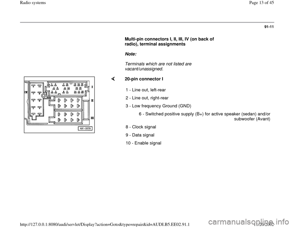
Multi-pin connectors I, II, III, IV (on back of
radio), terminal assignments
Note:
Terminals which are not listed are
vacant/unassigned.
20-pin connector I
1 - Line out, left-rear
2 - Line out, right-rear
3 - Low frequency Ground (GND)
6 - Switched positive supply (B+) for active speaker (sedan) and/or
subwoofer (Avant)
8 - Clock signal
9 - Data signal
10 - Enable signal
Pa
ge 13 of 45 Radio s
ystems
11/20/2002 htt
p://127.0.0.1:8080/audi/servlet/Dis
play?action=Goto&t
yp
e=re
pair&id=AUDI.B5.EE02.91.1
Page 14 of 45
91-12
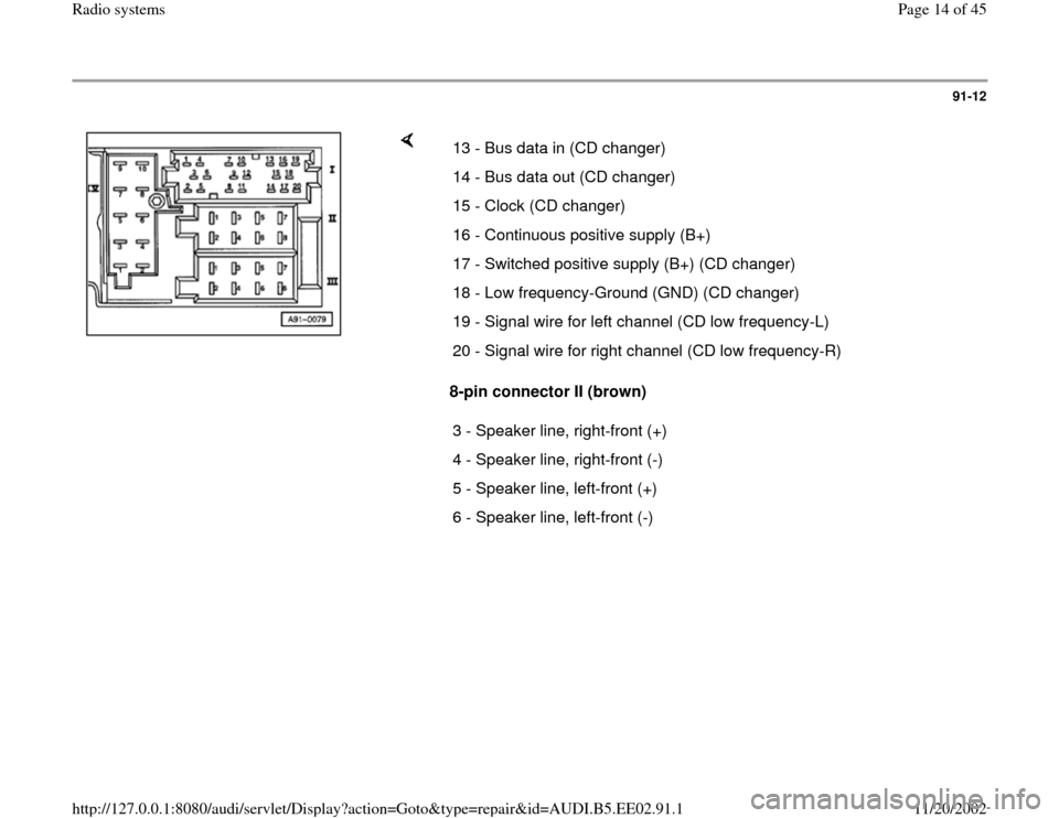
8-pin connector II (brown) 13 - Bus data in (CD changer)
14 - Bus data out (CD changer)
15 - Clock (CD changer)
16 - Continuous positive supply (B+)
17 - Switched positive supply (B+) (CD changer)
18 - Low frequency-Ground (GND) (CD changer)
19 - Signal wire for left channel (CD low frequency-L)
20 - Signal wire for right channel (CD low frequency-R)
3 - Speaker line, right-front (+)
4 - Speaker line, right-front (-)
5 - Speaker line, left-front (+)
6 - Speaker line, left-front (-)
Pa
ge 14 of 45 Radio s
ystems
11/20/2002 htt
p://127.0.0.1:8080/audi/servlet/Dis
play?action=Goto&t
yp
e=re
pair&id=AUDI.B5.EE02.91.1
Page 18 of 45
91-16
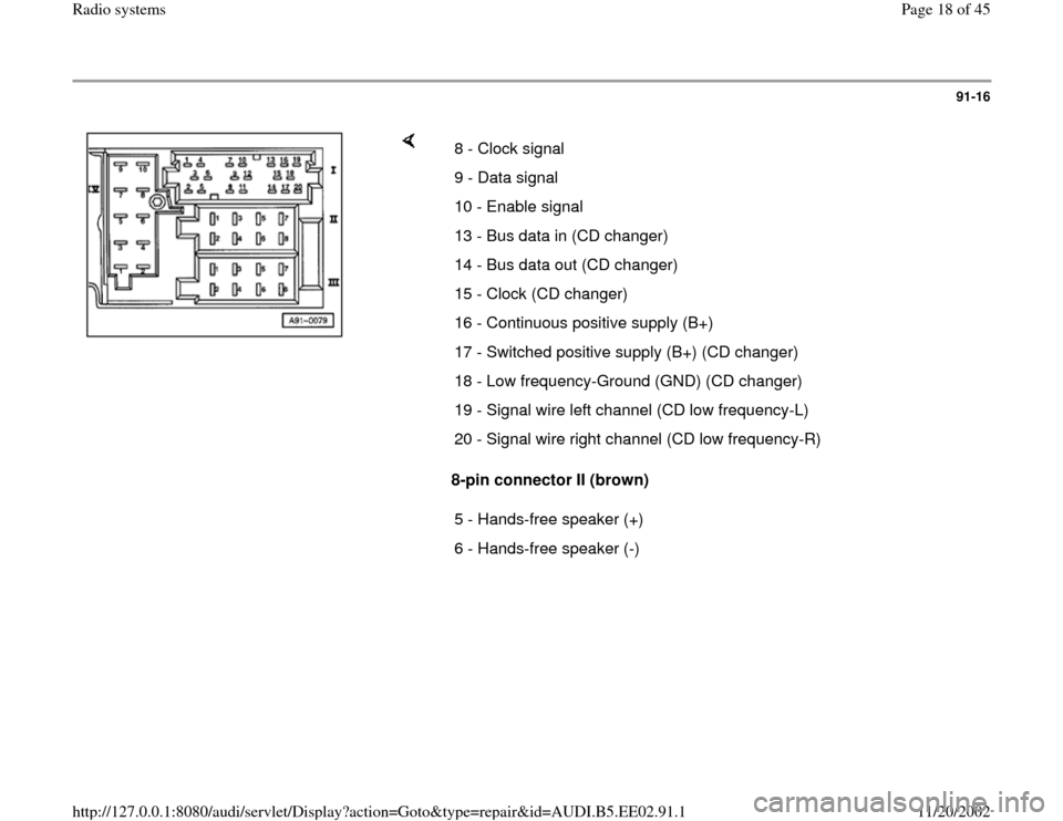
8-pin connector II (brown) 8 - Clock signal
9 - Data signal
10 - Enable signal
13 - Bus data in (CD changer)
14 - Bus data out (CD changer)
15 - Clock (CD changer)
16 - Continuous positive supply (B+)
17 - Switched positive supply (B+) (CD changer)
18 - Low frequency-Ground (GND) (CD changer)
19 - Signal wire left channel (CD low frequency-L)
20 - Signal wire right channel (CD low frequency-R)
5 - Hands-free speaker (+)
6 - Hands-free speaker (-)
Pa
ge 18 of 45 Radio s
ystems
11/20/2002 htt
p://127.0.0.1:8080/audi/servlet/Dis
play?action=Goto&t
yp
e=re
pair&id=AUDI.B5.EE02.91.1