wheel AUDI A4 1998 B5 / 1.G Suspension Front Axle Components Workshop Manual
[x] Cancel search | Manufacturer: AUDI, Model Year: 1998, Model line: A4, Model: AUDI A4 1998 B5 / 1.GPages: 26, PDF Size: 0.33 MB
Page 1 of 26
40-17
Front drive axles, removing
and installing
WARNING!
Do not re-use any fasteners that are worn or
deformed in normal use.
Some fasteners are designed to be used only
once, and are unreliable and may fail if used
a second time. This includes, but is not
limited to, nuts, bolts, washers, circlips and
cotter pins. Always follow the
recommendations in this manual-replace
these fasteners with new parts where
indicated, and any other time it is deemed
necessary by inspection.
Removing
- Remove wheel trim.
On light-alloy wheels use puller in vehicle tool kit
to remove trim cap
- Remove collar bolt for drive axle.
WARNING!
The vehicle must be standing on its wheels
Pa
ge 1 of 26 Front drive axles, removin
g and installin
g
11/20/2002 htt
p://127.0.0.1:8080/audi/servlet/Dis
play?action=Goto&t
yp
e=re
pair&id=AUDI.B5.SU01.40.3
Page 2 of 26
when loosening or tightening the collar bolt
for the drive axle (item - 17 -, page Page 40
-
4 ). Otherwise the risk of an accident exists.
- Remove wheel.
Pa
ge 2 of 26 Front drive axles, removin
g and installin
g
11/20/2002 htt
p://127.0.0.1:8080/audi/servlet/Dis
play?action=Goto&t
yp
e=re
pair&id=AUDI.B5.SU01.40.3
Page 3 of 26
40-18
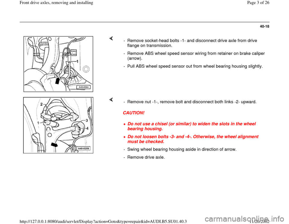
- Remove socket-head bolts -1- and disconnect drive axle from drive
flange on transmission.
- Remove ABS wheel speed sensor wiring from retainer on brake caliper
(arrow).
- Pull ABS wheel speed sensor out from wheel bearing housing slightly.
CAUTION! - Remove nut -1-, remove bolt and disconnect both links -2- upward.
Do not use a chisel (or similar) to widen the slots in the wheel
bearing housing. Do not loosen bolts -3- and -4-. Otherwise, the wheel alignment
must be checked.
- Swing wheel bearing housing aside in direction of arrow.
- Remove drive axle.
Pa
ge 3 of 26 Front drive axles, removin
g and installin
g
11/20/2002 htt
p://127.0.0.1:8080/audi/servlet/Dis
play?action=Goto&t
yp
e=re
pair&id=AUDI.B5.SU01.40.3
Page 4 of 26
40-19
Installing
- Install drive axle into wheel bearing housing and
bolt it to drive flange on transmission.
- Install both upper links and tighten nut to 40 Nm
(30 ft lb).
When tightening, press upper links downward as
far as possible
- Fully tighten bolts connecting drive axle to drive
flange on transmission.
M8 bolts: 40 Nm (30 ft lb)
M10 bolts: 80 Nm (59 ft lb)
- Push ABS wheel speed sensor into wheel
bearing housing up to stop and insert sensor
wiring into retainer on brake caliper.
- Install wheel.
- Install and tighten new bolt for drive axle.
M14 bolt: 115 Nm (85 ft lb) + 1/2-turn (180
Pa
ge 4 of 26 Front drive axles, removin
g and installin
g
11/20/2002 htt
p://127.0.0.1:8080/audi/servlet/Dis
play?action=Goto&t
yp
e=re
pair&id=AUDI.B5.SU01.40.3
Page 5 of 26
(180 )
M16 bolt: 190 Nm (140 ft lb) + 1/2-turn
(180 )
WARNING!
The vehicle must be standing on its wheels
when loosening or tightening the collar bolt
for the drive axle (item - 17 -, page Page 40
-
4 ). Otherwise the risk of an accident exists.
Pa
ge 5 of 26 Front drive axles, removin
g and installin
g
11/20/2002 htt
p://127.0.0.1:8080/audi/servlet/Dis
play?action=Goto&t
yp
e=re
pair&id=AUDI.B5.SU01.40.3
Page 11 of 26

40-24
Plastic CV joint boots
Special tools, test equipment and auxiliary
items
VAG1275 3207 VW411
VW401/402 VW412 VW522
40-204 A VAG1682 3340
On the Audi A4, new plastic CV joint boots are
installed on the 88 mm outer joint (wheel end) of
the front axle.
The plastic boots can be identified because they
are made out of a harder material than the
rubber boots.
The harder plastic boots necessitates the use of
stainless steel clamps for attaching the boots.
Pa
ge 11 of 26 Front drive axles, removin
g and installin
g
11/20/2002 htt
p://127.0.0.1:8080/audi/servlet/Dis
play?action=Goto&t
yp
e=re
pair&id=AUDI.B5.SU01.40.3
Page 18 of 26

40-31
4 -
Clamps
Always replaceTightening Fig.1
5 -
Boot for outer constant velocity joint
Check for splits and abrasionsBefore tightening clamp, briefly lift end of
boot to equalize pressure (ventilate) Fig. 3 As of chassis no. 8DTA 279 794, new
boots were introduced for 88 mm outer
joint (wheel end) Fig. 1
6 -
Clamp
Always replaceTightening Fig. 1
7 -
Spring washer
Installation position Fig. 5
Pa
ge 18 of 26 Front drive axles, removin
g and installin
g
11/20/2002 htt
p://127.0.0.1:8080/audi/servlet/Dis
play?action=Goto&t
yp
e=re
pair&id=AUDI.B5.SU01.40.3
Page 25 of 26
40-38
Plastic CV joint boots
On the Audi A4, new plastic CV joint boots are
installed on the 88 mm outer joint (wheel end) of
the front axle.
The plastic boots can be identified because they
are made out of a harder material than the
rubber boots.
The harder plastic boots necessitates the use of
stainless steel clamps for attaching the boots.
Instructions for stainless steel clamps only
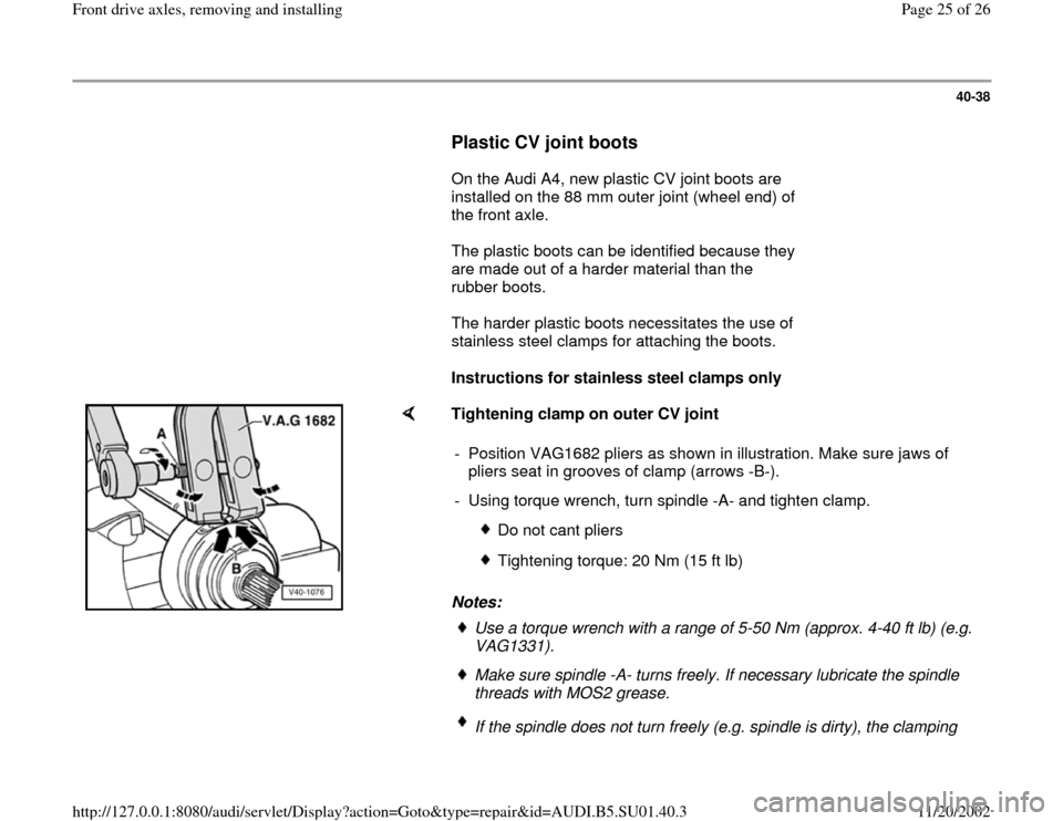
Tightening clamp on outer CV joint
Notes: - Position VAG1682 pliers as shown in illustration. Make sure jaws of
pliers seat in grooves of clamp (arrows -B-).
- Using torque wrench, turn spindle -A- and tighten clamp.
Do not cant pliers
Tightening torque: 20 Nm (15 ft lb)
Use a torque wrench with a range of 5-50 Nm (approx. 4-40 ft lb) (e.g.
VAG1331). Make sure spindle -A- turns freely. If necessary lubricate the spindle
threads with MOS2 grease. If the spindle does not turn freely (e.g. spindle is dirty), the clamping
Pa
ge 25 of 26 Front drive axles, removin
g and installin
g
11/20/2002 htt
p://127.0.0.1:8080/audi/servlet/Dis
play?action=Goto&t
yp
e=re
pair&id=AUDI.B5.SU01.40.3