wheel alignment AUDI A4 1998 B5 / 1.G Suspension Wheel Alignment User Guide
[x] Cancel search | Manufacturer: AUDI, Model Year: 1998, Model line: A4, Model: AUDI A4 1998 B5 / 1.GPages: 37, PDF Size: 0.41 MB
Page 16 of 37
44-18
Wheel alignment, preparations for
checking
Special tools, test requirements and auxiliary
items
VAG1907 VAG1941 VAG1925
VAG1925/3 VAG1925/4 VAG1925/6
Electronic alignment unit; e.g. VAG1813
- Carry out wheel run-out compensation.
Note:
On accident damaged vehicles, use special tool VAG1907 to make
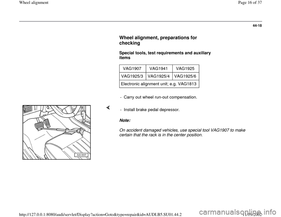
certain that the rack is in the center position. - Install brake pedal depressor.
Pa
ge 16 of 37 Wheel ali
gnment
11/19/2002 htt
p://127.0.0.1:8080/audi/servlet/Dis
play?action=Goto&t
yp
e=re
pair&id=AUDI.B5.SU01.44.2
Page 17 of 37
44-19
Wheel alignment, mandatory sequence
of operations for checking
Overview of sequence of operations for
measuring wheel alignment
Vehicle must only be measured at curb
weight
Note:
Exception: when measuring the toe-in curve as
described in the alignment program instructions.
The following work sequences must be
adhered to
1 - Check front axle camber centering and
adjust if necessary page 44
-24
.
2 - Check rear axle camber and adjust if
necessary:
FWD vehicles page 44
-20
AWD vehicles page 44
-22
3 - Check rear axle and adjust if necessary:
Pa
ge 17 of 37 Wheel ali
gnment
11/19/2002 htt
p://127.0.0.1:8080/audi/servlet/Dis
play?action=Goto&t
yp
e=re
pair&id=AUDI.B5.SU01.44.2
Page 19 of 37
44-20
Rear axle camber (front-wheel-drive
vehicles), checking
Wheel alignment specifications page 44
-11
.
The rear axle camber can be checked but not
adjusted on vehicles with front wheel drive.
If the readings are outside the allowable
tolerances the axle beam must be checked for
damage and replaced if necessary.
Pa
ge 19 of 37 Wheel ali
gnment
11/19/2002 htt
p://127.0.0.1:8080/audi/servlet/Dis
play?action=Goto&t
yp
e=re
pair&id=AUDI.B5.SU01.44.2
Page 20 of 37
44-21
Rear axle toe (front-wheel-drive
vehicles), centering
Individual toe settings on the rear axle cannot be
adjusted.
By moving the rear axle within the elongated
holes it is possible to center the individual toe
settings.
- Loosen securing bolts on mounting brackets.
- Center individual toe settings by moving axle
beam within elongated holes at mounting
brackets.
If the overall toe setting is outside the allowable
tolerance, or if it is not possible to center the
individual settings, the axle beam must be
checked for damage and replaced if necessary.
The body alignment must also be
checked/measured in the area of the rear axle
mounting points and serviced as necessary.
Repair Manual, Body Collision Repair
Pa
ge 20 of 37 Wheel ali
gnment
11/19/2002 htt
p://127.0.0.1:8080/audi/servlet/Dis
play?action=Goto&t
yp
e=re
pair&id=AUDI.B5.SU01.44.2
Page 21 of 37
44-22
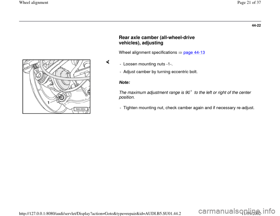
Rear axle camber (all-wheel-drive
vehicles), adjusting
Wheel alignment specifications page 44
-13
Note:
The maximum adjustment range is 90 to the left or right of the center
position. - Loosen mounting nuts -1-.
- Adjust camber by turning eccentric bolt.- Tighten mounting nut, check camber again and if necessary re-adjust.
Pa
ge 21 of 37 Wheel ali
gnment
11/19/2002 htt
p://127.0.0.1:8080/audi/servlet/Dis
play?action=Goto&t
yp
e=re
pair&id=AUDI.B5.SU01.44.2
Page 22 of 37
44-23
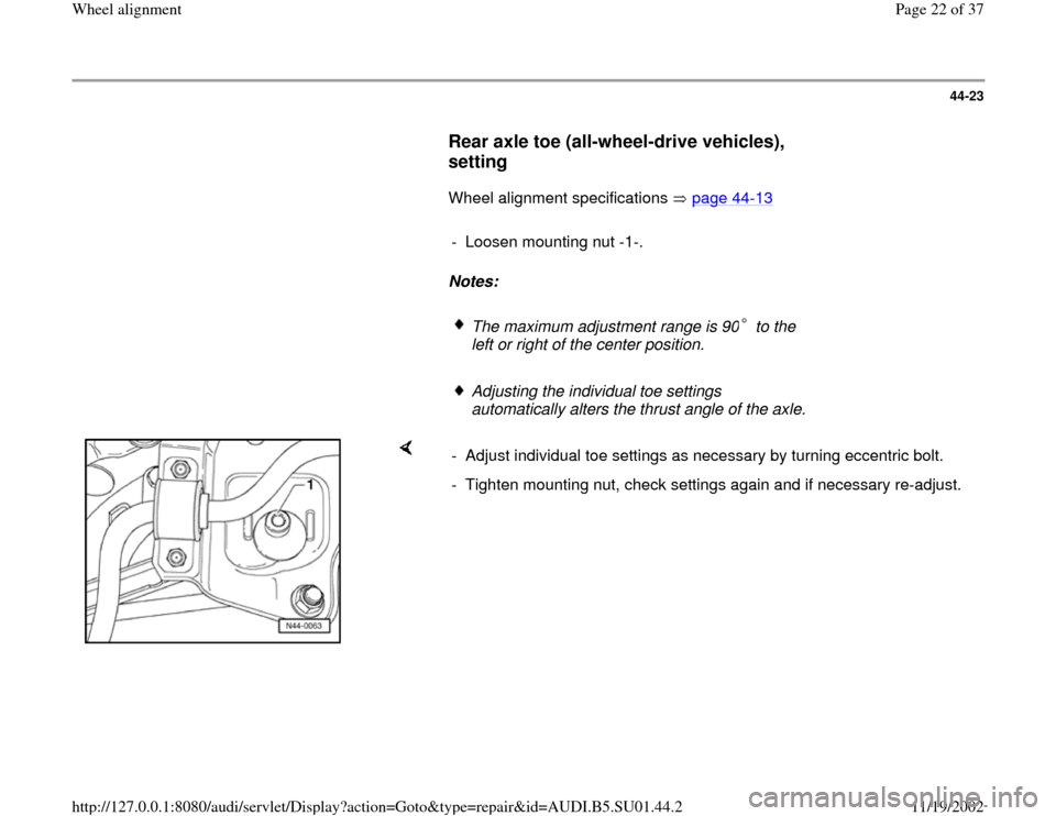
Rear axle toe (all-wheel-drive vehicles),
setting
Wheel alignment specifications page 44
-13
- Loosen mounting nut -1-.
Notes:
The maximum adjustment range is 90 to the
left or right of the center position.
Adjusting the individual toe settings
automatically alters the thrust angle of the axle.
- Adjust individual toe settings as necessary by turning eccentric bolt.
- Tighten mounting nut, check settings again and if necessary re-adjust.
Pa
ge 22 of 37 Wheel ali
gnment
11/19/2002 htt
p://127.0.0.1:8080/audi/servlet/Dis
play?action=Goto&t
yp
e=re
pair&id=AUDI.B5.SU01.44.2
Page 24 of 37
44-25
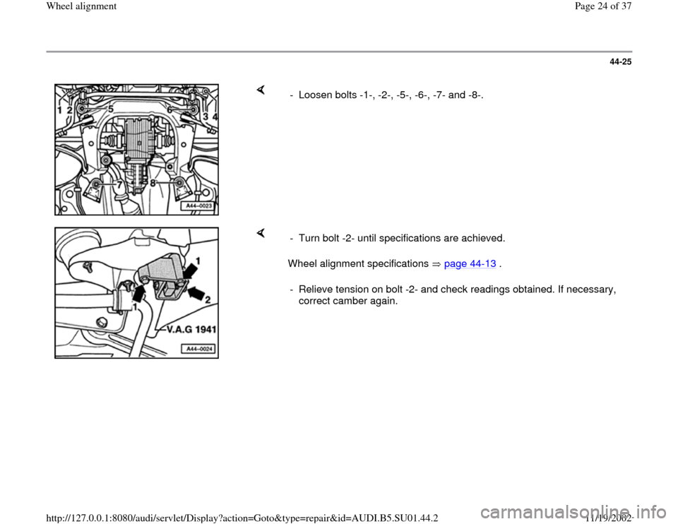
- Loosen bolts -1-, -2-, -5-, -6-, -7- and -8-.
Wheel alignment specifications page 44
-13
. - Turn bolt -2- until specifications are achieved.
- Relieve tension on bolt -2- and check readings obtained. If necessary,
correct camber again.
Pa
ge 24 of 37 Wheel ali
gnment
11/19/2002 htt
p://127.0.0.1:8080/audi/servlet/Dis
play?action=Goto&t
yp
e=re
pair&id=AUDI.B5.SU01.44.2
Page 25 of 37
44-26
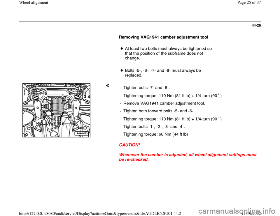
Removing VAG1941 camber adjustment tool
At least two bolts must always be tightened so
that the position of the subframe does not
change.
Bolts -5-, -6-, -7- and -8- must always be
replaced.
CAUTION!
Whenever the camber is adjusted, all wheel alignment settings must
be re-checked. - Tighten bolts -7- and -8-.
Tightening torque: 110 Nm (81 ft lb) + 1/4-turn (90 )- Remove VAG1941 camber adjustment tool.
- Tighten both forward bolts -5- and -6-.
Tightening torque: 110 Nm (81 ft lb) + 1/4-turn (90 )- Tighten bolts -1-, -2-, -3- and -4-.
Tightening torque: 60 Nm (44 ft lb)
Pa
ge 25 of 37 Wheel ali
gnment
11/19/2002 htt
p://127.0.0.1:8080/audi/servlet/Dis
play?action=Goto&t
yp
e=re
pair&id=AUDI.B5.SU01.44.2
Page 29 of 37
44-30
Setting suspension to starting position B1 (
page 44
-27
) on vehicles with standard
suspension (1BA), special suspension (1BC)
and heavy duty suspension (1BP)
Note:
Depending on the type of wheel alignment
equipment used, it may be necessary to raise the
front of the vehicle in order to position the
VAG1925 spacer. After lowering the vehicle
again the suspension must be bounced.
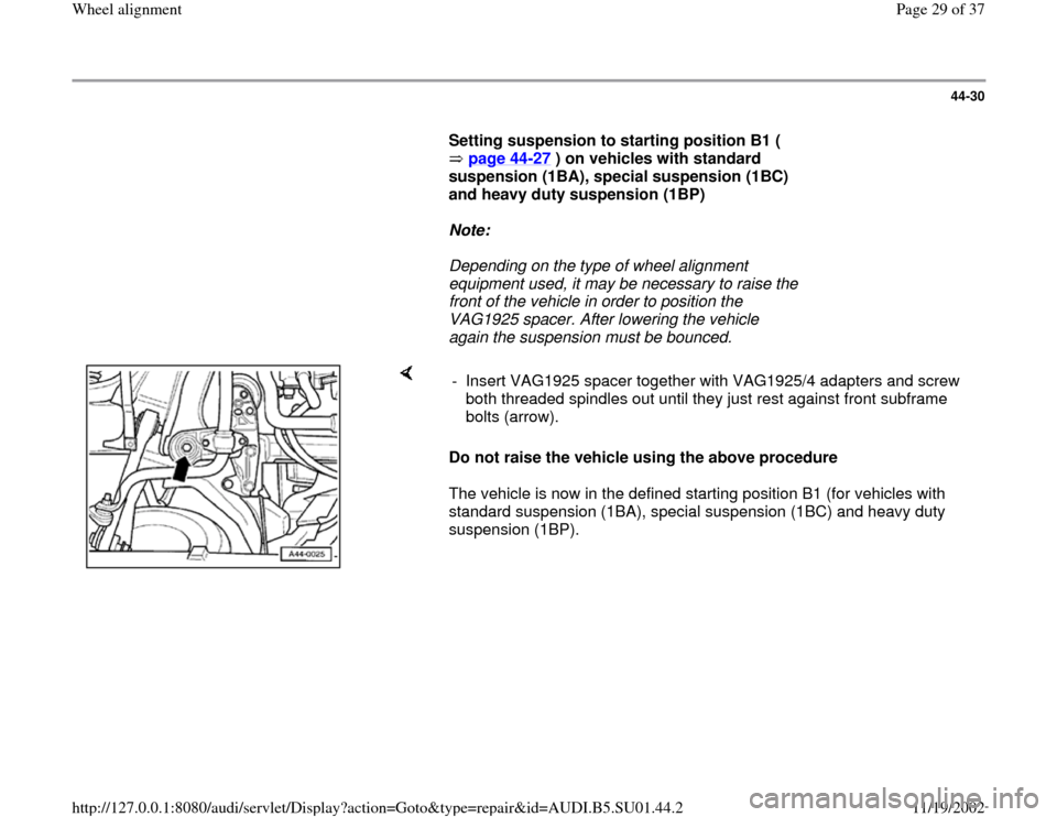
Do not raise the vehicle using the above procedure
The vehicle is now in the defined starting position B1 (for vehicles with
standard suspension (1BA), special suspension (1BC) and heavy duty
suspension (1BP). - Insert VAG1925 spacer together with VAG1925/4 adapters and screw
both threaded spindles out until they just rest against front subframe
bolts (arrow).
Pa
ge 29 of 37 Wheel ali
gnment
11/19/2002 htt
p://127.0.0.1:8080/audi/servlet/Dis
play?action=Goto&t
yp
e=re
pair&id=AUDI.B5.SU01.44.2
Page 30 of 37
44-31
Setting suspension to starting position B1 (
page 44
-27
) on vehicles with sport
suspension
Note:
Depending on the type of wheel alignment
equipment used, it may be necessary to raise the
front of the vehicle in order to position the
VAG1925 spacer. After lowering the vehicle
again the suspension must be bounced.
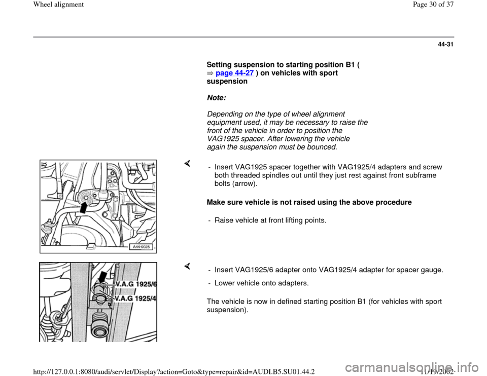
Make sure vehicle is not raised using the above procedure - Insert VAG1925 spacer together with VAG1925/4 adapters and screw
both threaded spindles out until they just rest against front subframe
bolts (arrow).
- Raise vehicle at front lifting points.
The vehicle is now in defined starting position B1 (for vehicles with sport
suspension). - Insert VAG1925/6 adapter onto VAG1925/4 adapter for spacer gauge.
- Lower vehicle onto adapters.
Pa
ge 30 of 37 Wheel ali
gnment
11/19/2002 htt
p://127.0.0.1:8080/audi/servlet/Dis
play?action=Goto&t
yp
e=re
pair&id=AUDI.B5.SU01.44.2