display AUDI A4 1999 B5 / 1.G AC System Electrical Testing Workshop Manual
[x] Cancel search | Manufacturer: AUDI, Model Year: 1999, Model line: A4, Model: AUDI A4 1999 B5 / 1.GPages: 47, PDF Size: 0.16 MB
Page 20 of 47

01-130
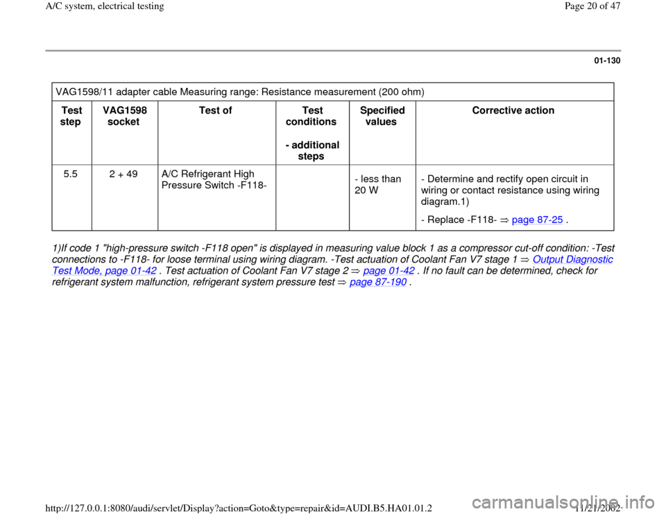
VAG1598/11 adapter cable Measuring range: Resistance measurement (200 ohm)
Test
step VAG1598
socket Test of
Test
conditions
- additional
steps Specified
values Corrective action
5.5 2 + 49 A/C Refrigerant High
Pressure Switch -F118-
- less than
20 W - Determine and rectify open circuit in
wiring or contact resistance using wiring
diagram.1)
- Replace -F118- page 87
-25
.
1)If code 1 "high-pressure switch -F118 open" is displayed in measuring value block 1 as a compressor cut-off condition: -Test
connections to -F118- for loose terminal using wiring diagram. -Test actuation of Coolant Fan V7 stage 1 Output Diagnostic Test Mode, page 01
-42
. Test actuation of Coolant Fan V7 stage 2 page 01
-42
. If no fault can be determined, check for
refrigerant system malfunction, refrigerant system pressure test page 87
-190
.
Pa
ge 20 of 47 A/C s
ystem, electrical testin
g
11/21/2002 htt
p://127.0.0.1:8080/audi/servlet/Dis
play?action=Goto&t
yp
e=re
pair&id=AUDI.B5.HA01.01.2
Page 37 of 47

01-145
Adapter cable VAG1598/11 connected.
Measuring range: Resistance measurement (200 ) Test
Step VAG1598
socket Test of
Test
conditions
- additional
work Specified
Value Corrective action
5.11 2 + 42 A/C pressure switch -
F129- (between
terminals 1 and 2)
Ignition
off - Less than
20
- Diagnose and repair open circuit or contact
resistance in wiring/connections using wiring
diagram.1).
- Check A/C pressure switch -F129- page 87
-67
.
1) If compressor cut-off condition code 1, "A/C pressure switch -F129- open" etc. appears in read measuring value block,
display group 1, display field 1: - check for intermittent contact in wiring/connections to -F129- using wiring diagram - check
function of Coolant Fan -V7- stage 1 with Output DTM (function
03)
page 01
-42
- check A/C pressure switch -F129- function
(actuation of -V7- stage 2, terminals 3 and 4 page 87
-67
). If no fault is determined, check A/C refrigerant system pressures
page 87
-190
.
Pa
ge 37 of 47 A/C s
ystem, electrical testin
g
11/21/2002 htt
p://127.0.0.1:8080/audi/servlet/Dis
play?action=Goto&t
yp
e=re
pair&id=AUDI.B5.HA01.01.2
Page 39 of 47

01-147
Notes:
The following test steps are only performed for A/C control heads -E87- with two displays:
Teststep 2.2 (the instrument panel interior temperature sensor -G56- is installed in A/C control heads -E87- with one
display)
Test step 5.7 (the interior temperature sensor fan -V42- is installed in A/C control heads -E87- with one display)
Switch on test area at VAG1526 multimeter: voltage test (20 V =)
VAG1598/11 adapter cable connected
Test
step VAG1598A
socket Test of
Test
requirements
- additional
operations Specified
value Corrective action
1.15
4) 46 + Ground
3) Power supply
terminal 58 of A/C
control head -E87-
Ignition
switched on Park light
switched on
approx.
battery
voltage - Locate and repair open circuit or short
circuit to Ground in wiring connection to
A/C control head -E87- using wiring
diagram
1.16
4) 46 + Ground
3) Power supply
terminal 58 of A/C
control head -E87-
Ignition
switched on Park light
- Locate and repair open circuit or short
circuit to Ground in wiring connection to
A/C control head -E87- using wiring
diagram.
Pa
ge 39 of 47 A/C s
ystem, electrical testin
g
11/21/2002 htt
p://127.0.0.1:8080/audi/servlet/Dis
play?action=Goto&t
yp
e=re
pair&id=AUDI.B5.HA01.01.2
Page 40 of 47

switched off
smaller
than 2 V
3) Ground is at, for example, connector D, socket 14 and 15. 4) Only perform this test step for an A/C control head with one display.
Pa
ge 40 of 47 A/C s
ystem, electrical testin
g
11/21/2002 htt
p://127.0.0.1:8080/audi/servlet/Dis
play?action=Goto&t
yp
e=re
pair&id=AUDI.B5.HA01.01.2
Page 41 of 47

01-148
Switch on test area at VAG1526 multimeter: voltage test (20 V)
VAG1598/12 adapter cable connected
Test
step VAG1598A
socket Test of
Test
requirements
- additional
operations Specified
value Corrective action
1.17
4) 8
+
14
Terminal 15 and Ground
connection at A/C control head
-E87- (power supply for A/C
clutch)
Ignition
switched on
approx.
battery
voltage - Repair power supply or
Ground connection
according to wiring
diagram
4) Only perform this test step for an A/C control head with one display.
Pa
ge 41 of 47 A/C s
ystem, electrical testin
g
11/21/2002 htt
p://127.0.0.1:8080/audi/servlet/Dis
play?action=Goto&t
yp
e=re
pair&id=AUDI.B5.HA01.01.2
Page 46 of 47

01-152
Voltage test - switch multimeter to 20V measuring range
VAG1598/11 adapter cable connected
Test
step VAG1598
sockets Test of
Test conditions
- additional
operations Specified
value Corrective action
1.13 45 +
GND Terminal 58d on -
E87-
Ignition switched
on Parking light
switched on 0 to12 V
- Repair open circuit or short circuit
according to wiring diagram.
1.14 45 +
GND Terminal 58d on -
E87- Ignition switched
on Parking light
switched off 0 to 12 V
- Repair open circuit or short circuit
according to wiring diagram.
Notes:
Test steps 1.11 - 1.14 apply for vehicles beginning m.y. 1998 (A/C control head with Part No 8L0 820 043 from Part No.
index letter "D").
The Ground connection can be made via connector D, terminals 14 and 15 (for example).
The voltage to terminal 58d is created as a square-wave signal from the instrument cluster. The brightness of the display
on A/C control head -E87- is determined by the period of activation. The multimeter will indicate the average value.
Pa
ge 46 of 47 A/C s
ystem, electrical testin
g
11/21/2002 htt
p://127.0.0.1:8080/audi/servlet/Dis
play?action=Goto&t
yp
e=re
pair&id=AUDI.B5.HA01.01.2