lock AUDI A4 1999 B5 / 1.G AEB ATW Engines Turbocharger System Workshop Manual
[x] Cancel search | Manufacturer: AUDI, Model Year: 1999, Model line: A4, Model: AUDI A4 1999 B5 / 1.GPages: 50, PDF Size: 0.63 MB
Page 1 of 50
21-1
Turbocharger system
Note:
Observe rules of cleanliness Page 21
-22
.
Charge air pressure control connection diagram
Page 21
-2 .
All hose connections are secured with hose
clamps:
parts catalog.
charge air pressure system must be free of
leaks.
Replace self-locking nuts.
Always replace gaskets.
Pa
ge 1 of 50 Turbochar
ger s
ystem
11/18/2002 htt
p://127.0.0.1:8080/audi/servlet/Dis
play?action=Goto&t
yp
e=re
pair&id=AUDI.B5.GE02.21.1
Page 13 of 50
21-11
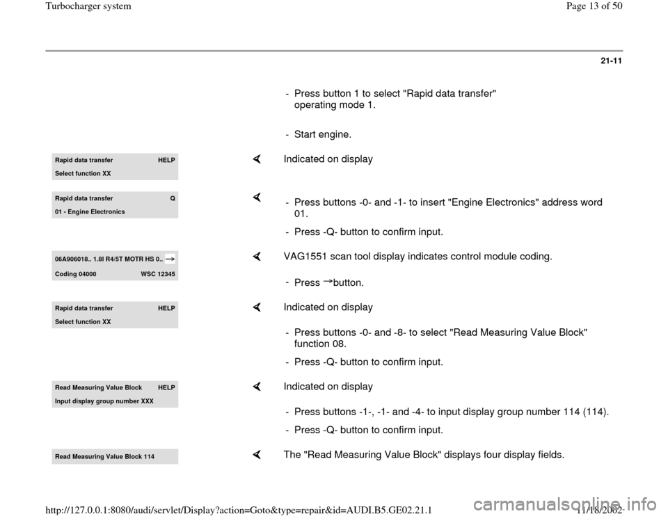
- Press button 1 to select "Rapid data transfer"
operating mode 1.
- Start engine.Rapid data transfer
HELP
Select function XX
Indicated on display
Rapid data transfer
Q
01 - En
gine Electronics
- Press buttons -0- and -1- to insert "Engine Electronics" address word
01.
- Press -Q- button to confirm input.
06A906018.. 1.8l R4/5T MOTR HS 0.. Codin
g 04000
WSC 12345
VAG1551 scan tool display indicates control module coding.
-
Press button.
Rapid data transfer
HELP
Select function XX
Indicated on display
- Press buttons -0- and -8- to select "Read Measuring Value Block"
function 08.
- Press -Q- button to confirm input.
Read Measuring Value Block
HELP
Input displa
y group number XXX
Indicated on display
- Press buttons -1-, -1- and -4- to input display group number 114 (114).
- Press -Q- button to confirm input.
Read Measuring Value Block 114
The "Read Measuring Value Block" displays four display fields.
Pa
ge 13 of 50 Turbochar
ger s
ystem
11/18/2002 htt
p://127.0.0.1:8080/audi/servlet/Dis
play?action=Goto&t
yp
e=re
pair&id=AUDI.B5.GE02.21.1
Page 15 of 50
21-12
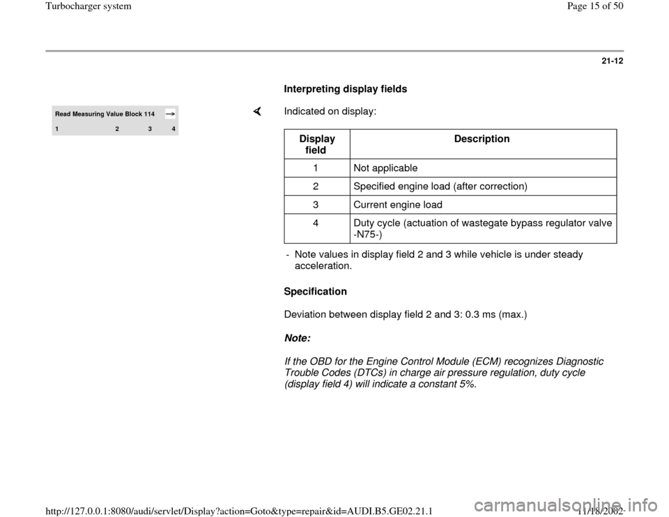
Interpreting display fields Read Measuring Value Block 114 1
2
3
4
Indicated on display:
Specification
Deviation between display field 2 and 3: 0.3 ms (max.)
Note:
If the OBD for the Engine Control Module (ECM) recognizes Diagnostic
Trouble Codes (DTCs) in charge air pressure regulation, duty cycle
(display field 4) will indicate a constant 5%.
Display
field Description
1 Not applicable
2 Specified engine load (after correction)
3 Current engine load
4 Duty cycle (actuation of wastegate bypass regulator valve
-N75-)
- Note values in display field 2 and 3 while vehicle is under steady
acceleration.
Pa
ge 15 of 50 Turbochar
ger s
ystem
11/18/2002 htt
p://127.0.0.1:8080/audi/servlet/Dis
play?action=Goto&t
yp
e=re
pair&id=AUDI.B5.GE02.21.1
Page 31 of 50
21-23
Note:
Observe rules of cleanliness Page 21
-22
.
Charge air pressure control connection diagram
Page 21
-2 .
All hose connections are secured with hose
clamps that comply with factory specifications
parts catalog.
Charge air pressure system must be free of
leaks.
Always replace gaskets and self-locking nuts.
Pa
ge 31 of 50 Turbochar
ger s
ystem
11/18/2002 htt
p://127.0.0.1:8080/audi/servlet/Dis
play?action=Goto&t
yp
e=re
pair&id=AUDI.B5.GE02.21.1
Page 39 of 50
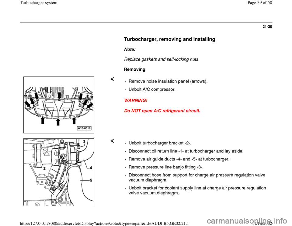
21-30
Turbocharger, removing and installing
Note:
Replace gaskets and self-locking nuts.
Removing
WARNING!
Do NOT open A/C refrigerant circuit. - Remove noise insulation panel (arrows).
- Unbolt A/C compressor.
- Unbolt turbocharger bracket -2-.
- Disconnect oil return line -1- at turbocharger and lay aside.
- Remove air guide ducts -4- and -5- at turbocharger.
- Remove pressure line banjo fitting -3-.
- Disconnect hose from support for charge air pressure regulation valve
vacuum diaphragm.
- Unbolt bracket for coolant supply line at charge air pressure regulation
valve vacuum diaphragm.
Pa
ge 39 of 50 Turbochar
ger s
ystem
11/18/2002 htt
p://127.0.0.1:8080/audi/servlet/Dis
play?action=Goto&t
yp
e=re
pair&id=AUDI.B5.GE02.21.1
Page 46 of 50
21-34
Tightening torques
Component
Tightening
torques
Oil return line to turbocharger 10 Nm (7 ft
lb)
Turbocharger bracket to
turbocharger (bolt and washer
assembly M8)
1) 40 Nm (30 ft
lb)
Turbocharger bracket to cylinder
block 45 Nm (33 ft
lb)
Oil feed line to turbocharger 25 Nm (18 ft
lb)
Coolant supply pipe bracket to
turbocharger 10 Nm (7 ft
lb)
Oil supply line bracket to cylinder
head 20 Nm (15 ft
lb)
Coolant supply line to
turbocharger 25 Nm (18 ft
lb)
Crankcase ventilation line to
cylinder head 10 Nm (7 ft
lb)
Coolant return line to
turbocharger 30 Nm (22 ft
lb)
Turbocharger to exhaust
manifold 35 Nm (26 ft
lb)
Three Way Catalytic Converter 30 Nm (22 ft
Pa
ge 46 of 50 Turbochar
ger s
ystem
11/18/2002 htt
p://127.0.0.1:8080/audi/servlet/Dis
play?action=Goto&t
yp
e=re
pair&id=AUDI.B5.GE02.21.1
Page 50 of 50
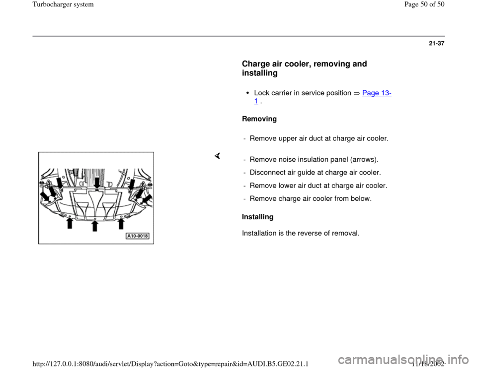
21-37
Charge air cooler, removing and
installing
Lock carrier in service position Page 13
-
1 .
Removing
- Remove upper air duct at charge air cooler.
Installing
Installation is the reverse of removal. - Remove noise insulation panel (arrows).
- Disconnect air guide at charge air cooler.
- Remove lower air duct at charge air cooler.
- Remove charge air cooler from below.
Pa
ge 50 of 50 Turbochar
ger s
ystem
11/18/2002 htt
p://127.0.0.1:8080/audi/servlet/Dis
play?action=Goto&t
yp
e=re
pair&id=AUDI.B5.GE02.21.1