check oil AUDI A4 1999 B5 / 1.G AEB ATW Engines Valvetrain Servicing Workshop Manual
[x] Cancel search | Manufacturer: AUDI, Model Year: 1999, Model line: A4, Model: AUDI A4 1999 B5 / 1.GPages: 51, PDF Size: 0.8 MB
Page 2 of 51
15-33
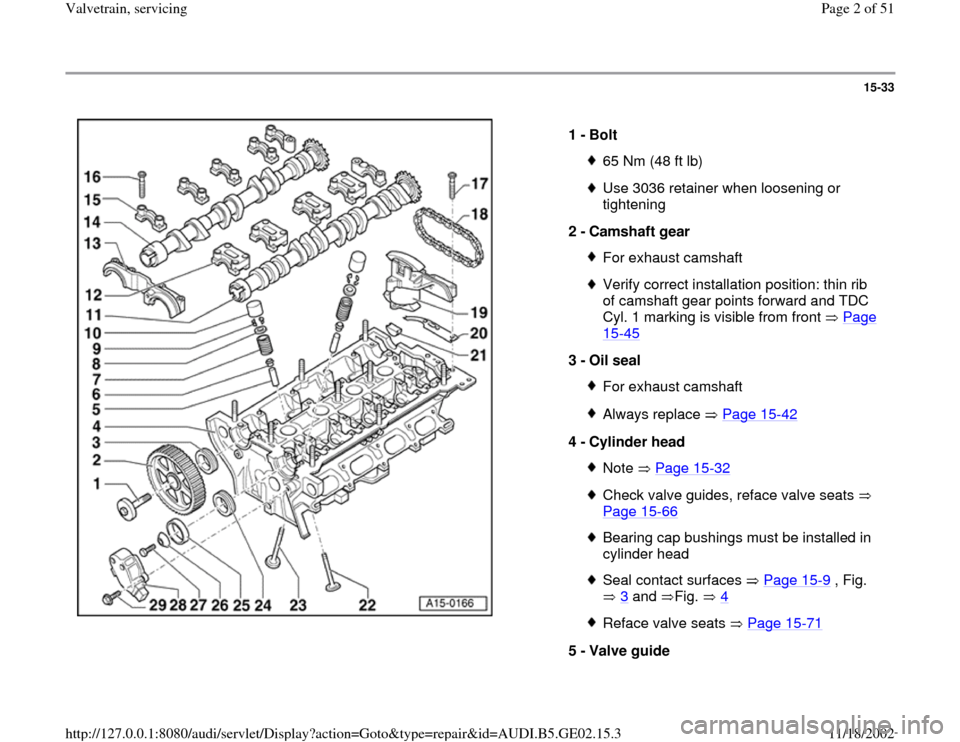
1 -
Bolt
65 Nm (48 ft lb)Use 3036 retainer when loosening or
tightening
2 -
Camshaft gear For exhaust camshaftVerify correct installation position: thin rib
of camshaft gear points forward and TDC
Cyl. 1 marking is visible from front Page 15
-45
3 -
Oil seal
For exhaust camshaftAlways replace Page 15
-42
4 -
Cylinder head
Note Page 15
-32
Check valve guides, reface valve seats
Page 15
-66
Bearing cap bushings must be installed in
cylinder head Seal contact surfaces Page 15
-9 , Fig.
3
and Fig. 4
Reface valve seats Page 15
-71
5 -
Valve guide
Pa
ge 2 of 51 Valvetrain, servicin
g
11/18/2002 htt
p://127.0.0.1:8080/audi/servlet/Dis
play?action=Goto&t
yp
e=re
pair&id=AUDI.B5.GE02.15.3
Page 4 of 51
15-34
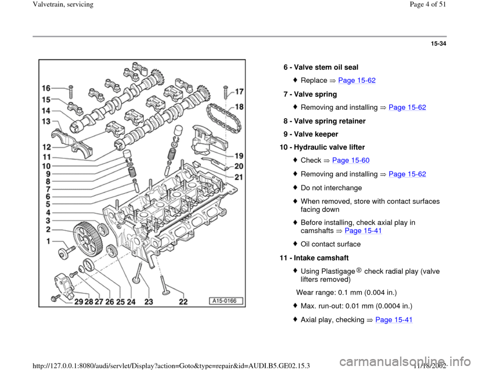
6 -
Valve stem oil seal
Replace Page 15
-62
7 -
Valve spring
Removing and installing Page 15
-62
8 -
Valve spring retainer
9 -
Valve keeper
10 -
Hydraulic valve lifter
Check Page 15
-60
Removing and installing Page 15
-62
Do not interchangeWhen removed, store with contact surfaces
facing down Before installing, check axial play in
camshafts Page 15
-41
Oil contact surface
11 -
Intake camshaft Using Plastigage check radial play (valve
lifters removed)
Wear range: 0.1 mm (0.004 in.)
Max. run-out: 0.01 mm (0.0004 in.)Axial play, checking Page 15
-41Pa
ge 4 of 51 Valvetrain, servicin
g
11/18/2002 htt
p://127.0.0.1:8080/audi/servlet/Dis
play?action=Goto&t
yp
e=re
pair&id=AUDI.B5.GE02.15.3
Page 9 of 51
15-38
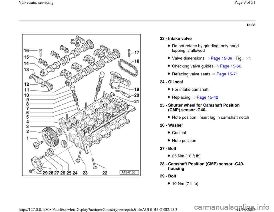
23 -
Intake valve
Do not reface by grinding; only hand
lapping is allowed Valve dimensions Page 15
-39
, Fig. 1
Checking valve guides Page 15
-66
Refacing valve seats Page 15
-71
24 -
Oil seal
For intake camshaftReplacing Page 15
-42
25 -
Shutter wheel for Camshaft Position
(CMP) sensor -G40-
Note position: insert lug in camshaft notch
26 -
Washer ConicalNote position
27 -
Bolt 25 Nm (18 ft lb)
28 -
Camshaft Position (CMP) sensor -G40-
housing
29 -
Bolt 10 Nm (7 ft lb)
Pa
ge 9 of 51 Valvetrain, servicin
g
11/18/2002 htt
p://127.0.0.1:8080/audi/servlet/Dis
play?action=Goto&t
yp
e=re
pair&id=AUDI.B5.GE02.15.3
Page 31 of 51
15-57
- Remove 3366 bracket-tensioner.
CAUTION!
Part numbers are listed here for reference only. Always check with
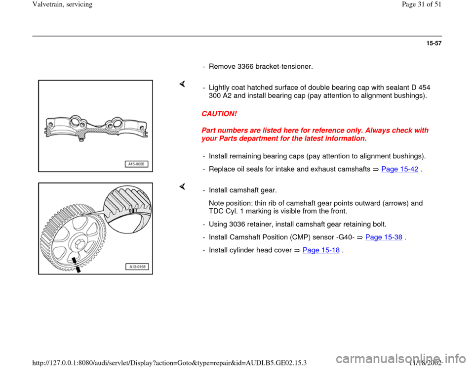
your Parts department for the latest information. - Lightly coat hatched surface of double bearing cap with sealant D 454
300 A2 and install bearing cap (pay attention to alignment bushings).
- Install remaining bearing caps (pay attention to alignment bushings).
- Replace oil seals for intake and exhaust camshafts Page 15
-42
.
- Install camshaft gear.
Note position: thin rib of camshaft gear points outward (arrows) and
TDC Cyl. 1 marking is visible from the front.
- Using 3036 retainer, install camshaft gear retaining bolt.
- Install Camshaft Position (CMP) sensor -G40- Page 15
-38
.
- Install cylinder head cover Page 15
-18
.
Pa
ge 31 of 51 Valvetrain, servicin
g
11/18/2002 htt
p://127.0.0.1:8080/audi/servlet/Dis
play?action=Goto&t
yp
e=re
pair&id=AUDI.B5.GE02.15.3
Page 34 of 51
15-60
Hydraulic valve lifters, checking
Special tools and equipment
Feeler gauge
Wood or plastic wedge
Note:
Hydraulic valve lifters cannot be serviced.
Irregular valve noise when starting engine is
normal.
- Start engine and let run until coolant
temperature reaches at least 80 C (176 F).
- Increase RPM to 2500 for about 2 minutes; if
necessary test drive vehicle.
Note:
If irregular valve noises disappear but then
reappear during drive, replace oil retaining valve.
Oil retaining valve is located in oil filter bracket
Page 17
-6 .
If hydraulic valve lifters are still loud, locate faulty
Pa
ge 34 of 51 Valvetrain, servicin
g
11/18/2002 htt
p://127.0.0.1:8080/audi/servlet/Dis
play?action=Goto&t
yp
e=re
pair&id=AUDI.B5.GE02.15.3