engine AUDI A4 1999 B5 / 1.G AFC Engine Lock Carrier Removing For Service Workshop Manual
[x] Cancel search | Manufacturer: AUDI, Model Year: 1999, Model line: A4, Model: AUDI A4 1999 B5 / 1.GPages: 35, PDF Size: 0.44 MB
Page 7 of 35
15-13
Cylinder head, removing and installing
Engine installed
This removal procedure refers to the left cylinder
head
Removing
- Remove ribbed belt page 13
-9
- Remove toothed belt page 13
-11
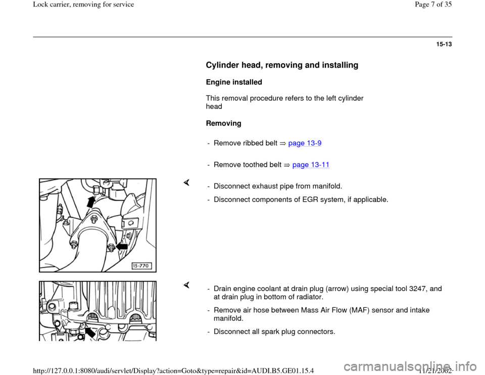
- Disconnect exhaust pipe from manifold.
- Disconnect components of EGR system, if applicable.
- Drain engine coolant at drain plug (arrow) using special tool 3247, and
at drain plug in bottom of radiator.
- Remove air hose between Mass Air Flow (MAF) sensor and intake
manifold.
- Disconnect all spark plug connectors.
Pa
ge 7 of 35 Lock carrier, removin
g for service
11/21/2002 htt
p://127.0.0.1:8080/audi/servlet/Dis
play?action=Goto&t
yp
e=re
pair&id=AUDI.B5.GE01.15.4
Page 11 of 35
15-15
- Disconnect harness connectors for Heated
Oxygen Sensors (H02S) and oxygen sensor
heaters at engine compartment bulkhead, and
move to one side.
- Disconnect vacuum line to EGR vacuum
regulator solenoid valve at throttle body.
- Remove EGR valve from intake manifold.
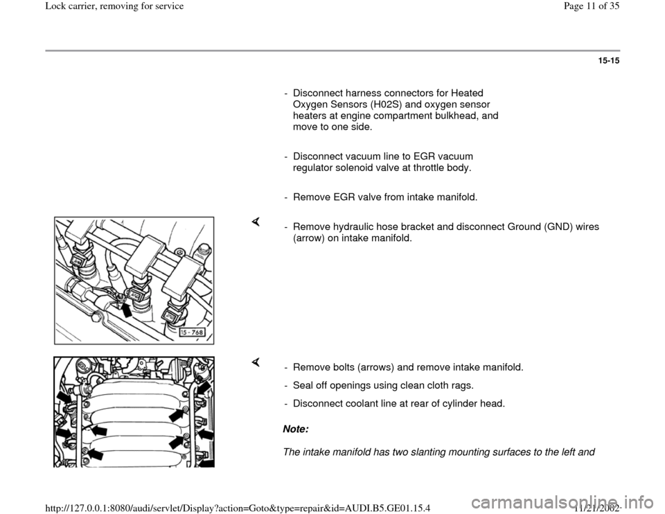
- Remove hydraulic hose bracket and disconnect Ground (GND) wires
(arrow) on intake manifold.
Note:
The intake manifold has two slanting mounting surfaces to the left and - Remove bolts (arrows) and remove intake manifold.
- Seal off openings using clean cloth rags.
- Disconnect coolant line at rear of cylinder head.
Pa
ge 11 of 35 Lock carrier, removin
g for service
11/21/2002 htt
p://127.0.0.1:8080/audi/servlet/Dis
play?action=Goto&t
yp
e=re
pair&id=AUDI.B5.GE01.15.4
Page 16 of 35
15-18
Compression pressure, checking
Engine warm-oil temperature at least 30 C
(86 F)
Throttle valve fully open during cranking
- Disconnect harness connectors from ignition coil
power output stage and from all six fuel
injectors.
- Use compression pressure recorder VAG 1381
together with adapter 1381/5 or equivalent to
measure compression.
Note:
Refer to operating instructions for use of the
recorder.
- Operate starter until tester shows no additional
increase in pressure.
Compression pressures
New: 9-14 bar (131-203 psi)
Wear limit: 7.5 bar (109 psi)
Pa
ge 16 of 35 Lock carrier, removin
g for service
11/21/2002 htt
p://127.0.0.1:8080/audi/servlet/Dis
play?action=Goto&t
yp
e=re
pair&id=AUDI.B5.GE01.15.4
Page 20 of 35
15-20
Installing
Tightening torque: 17 Nm (15 ft lb)
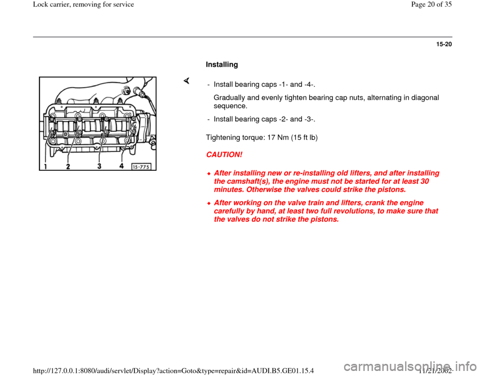
CAUTION! - Install bearing caps -1- and -4-.
Gradually and evenly tighten bearing cap nuts, alternating in diagonal
sequence.
- Install bearing caps -2- and -3-.
After installing new or re-installing old lifters, and after installing
the camshaft(s), the engine must not be started for at least 30
minutes. Otherwise the valves could strike the pistons. After working on the valve train and lifters, crank the engine
carefully by hand, at least two full revolutions, to make sure that
the valves do not strike the pistons.
Pa
ge 20 of 35 Lock carrier, removin
g for service
11/21/2002 htt
p://127.0.0.1:8080/audi/servlet/Dis
play?action=Goto&t
yp
e=re
pair&id=AUDI.B5.GE01.15.4
Page 22 of 35
15-22
Hydraulic valve lifters, checking
Note:
Irregular valve noise during cranking is
normal.
Do not interchange hydraulic lifters. If
necessary mark them when they are being
removed.
Place lifters that have been removed on a clean
surface with the contact surface (camshaft end)
facing downward.
Hydraulic lifters cannot be repaired or adjusted.
Faulty lifters must be replaced.
- Start and run engine until warm-until radiator
coolant fan has come on at least once.
- Increase engine speed to approx. 2500 RPM for
2 minutes
If the irregular valve noise stops and then re-
occurs again each time vehicle is used in stop
and go traffic:
-
Replace the oil check valves Repair Group
Pa
ge 22 of 35 Lock carrier, removin
g for service
11/21/2002 htt
p://127.0.0.1:8080/audi/servlet/Dis
play?action=Goto&t
yp
e=re
pair&id=AUDI.B5.GE01.15.4
Page 24 of 35
15-23
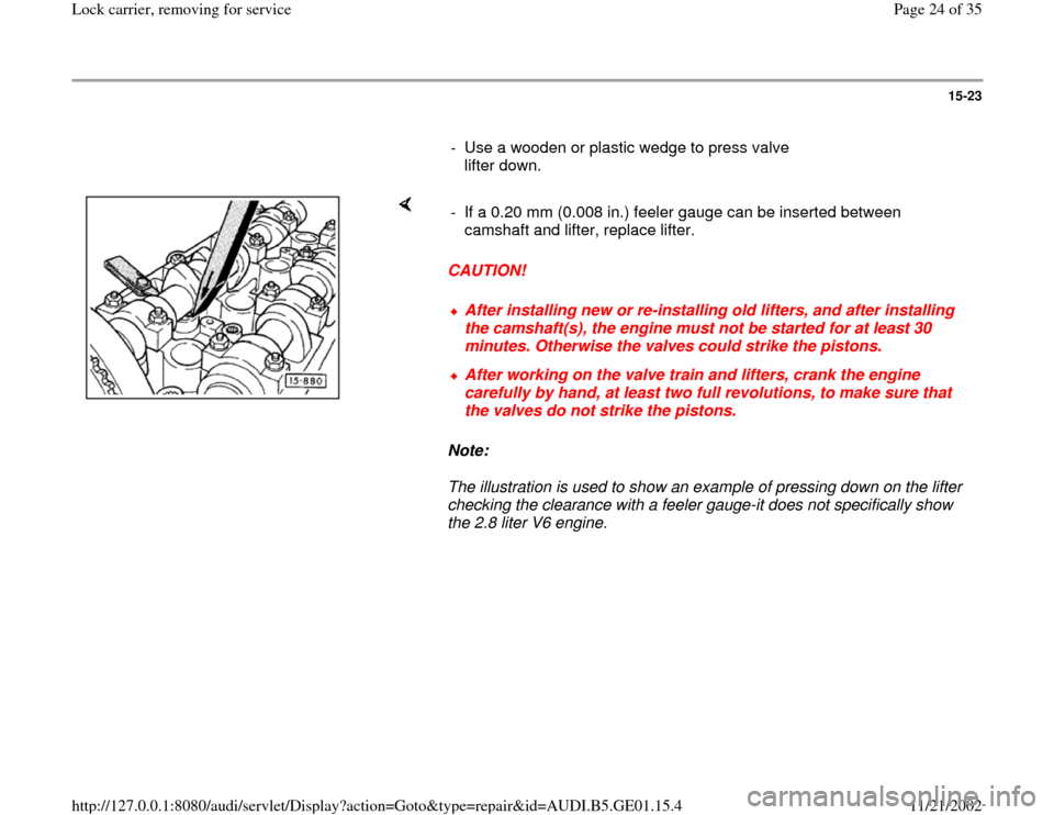
- Use a wooden or plastic wedge to press valve
lifter down.
CAUTION!
Note:
The illustration is used to show an example of pressing down on the lifter
checking the clearance with a feeler gauge-it does not specifically show
the 2.8 liter V6 engine. - If a 0.20 mm (0.008 in.) feeler gauge can be inserted between
camshaft and lifter, replace lifter.
After installing new or re-installing old lifters, and after installing
the camshaft(s), the engine must not be started for at least 30
minutes. Otherwise the valves could strike the pistons. After working on the valve train and lifters, crank the engine
carefully by hand, at least two full revolutions, to make sure that
the valves do not strike the pistons.
Pa
ge 24 of 35 Lock carrier, removin
g for service
11/21/2002 htt
p://127.0.0.1:8080/audi/servlet/Dis
play?action=Goto&t
yp
e=re
pair&id=AUDI.B5.GE01.15.4
Page 31 of 35
15-29
Valve guides, checking and replacing
Checking
When repairing engines with low compression
due to leaking valves, it is not sufficient to reface
or replace the valve seats and valves. It is also
necessary to check the valve guides for wear.
This is particularly important when checking
engines with high mileage.
- Insert new valve into guide until end of valve
stem is flush with end of guide.
CAUTION!
Due to the difference in valve stem diameters,
make sure that only an intake valve is used to
check intake valve guides, and that only an
exhaust valve is used to check the exhaust
valve guides.
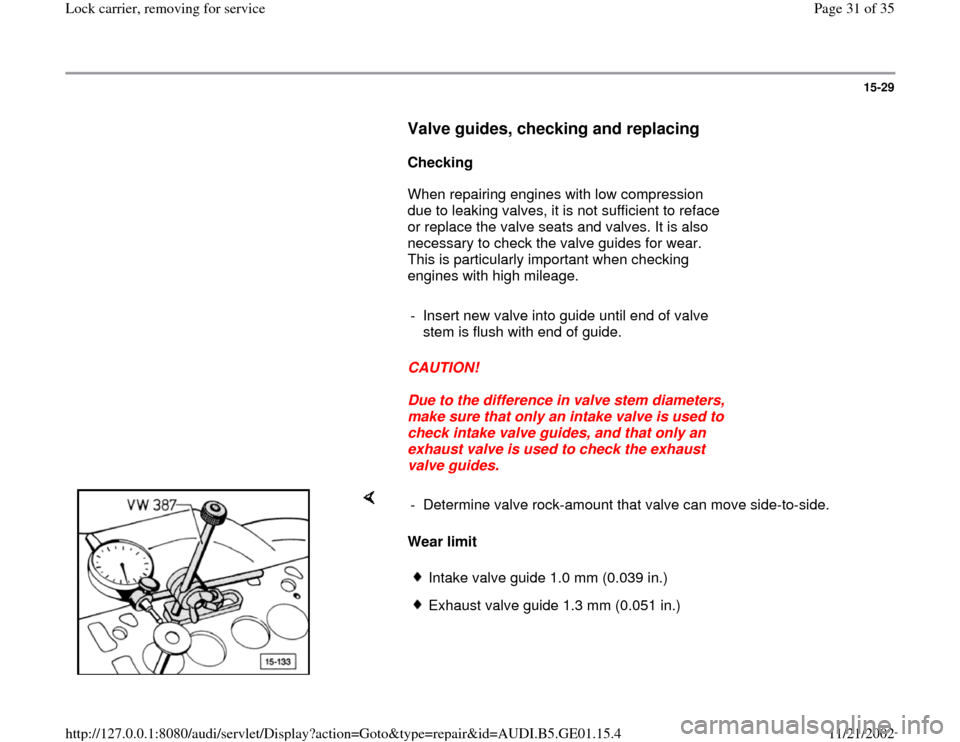
Wear limit - Determine valve rock-amount that valve can move side-to-side.
Intake valve guide 1.0 mm (0.039 in.)Exhaust valve guide 1.3 mm (0.051 in.)
Pa
ge 31 of 35 Lock carrier, removin
g for service
11/21/2002 htt
p://127.0.0.1:8080/audi/servlet/Dis
play?action=Goto&t
yp
e=re
pair&id=AUDI.B5.GE01.15.4