ECO mode AUDI A4 1999 B5 / 1.G AFC Engine On Board Diagnostic Multiport Fuel Injection Workshop Manual
[x] Cancel search | Manufacturer: AUDI, Model Year: 1999, Model line: A4, Model: AUDI A4 1999 B5 / 1.GPages: 366, PDF Size: 1.21 MB
Page 5 of 366
01-3
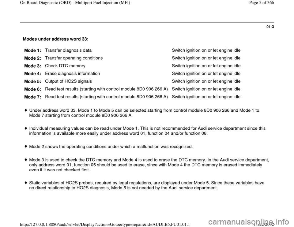
Modes under address word 33:
Mode 1: Transfer diagnosis data Switch ignition on or let engine idle
Mode 2: Transfer operating conditions Switch ignition on or let engine idle
Mode 3: Check DTC memory Switch ignition on or let engine idle
Mode 4: Erase diagnosis information Switch ignition on or let engine idle
Mode 5: Output of HO2S signals Switch ignition on or let engine idle
Mode 6: Read test results (starting with control module 8D0 906 266 A) Switch ignition on or let engine idle
Mode 7: Read test results (starting with control module 8D0 906 266 A) Switch ignition on or let engine idle
Under address word 33, Mode 1 to Mode 5 can be selected starting from control module 8D0 906 266 and Mode 1 to
Mode 7 starting from control module 8D0 906 266 A.
Individual measuring values can be read under Mode 1. This is not recommended for Audi service department since this
information is available more easily under address word 01, function 04 and/or function 08.
Mode 2 shows the operating conditions under which a malfunction was recognized.
Mode 3 is used to check the DTC memory and Mode 4 is used to erase the DTC memory. In the Audi service department,
only address word 01, function 05 should be used to erase, since with Mode 4 the DTC memory is erased immediately
even if it was not checked first.
Static variables of HO2S probes, required by legal regulations, are displayed under Mode 5. Since these variables have
no direct relationship to HO2S diagnosis, Mode 5 is not needed by the Audi service department.
Pa
ge 5 of 366 On Board Dia
gnostic
(OBD
) - Multi
port Fuel In
jection
(MFI
)
11/22/2002 htt
p://127.0.0.1:8080/audi/servlet/Dis
play?action=Goto&t
yp
e=re
pair&id=AUDI.B5.FU01.01.1
Page 8 of 366
01-5
Malfunction recognition and repair
Notes:
Before initiating the On Board Diagnostic (OBD) program, and before testing wiring and replacing components, check the
following ground connections for corrosion and damaged connections and repair them if necessary
- Check ground connections on intake manifold
- Battery ground strap OK
- Ground cable between engine and body OK Malfunction recognition and repair is described for the VAG 1551 scan tool, since it offers significantly more functions.
However, malfunction recognition and repair is also possible with a "generic" scan tool.
A specific procedure must be used to evaluate malfunctions, since the engine electronics can be checked with address
word 01 and address word 33 on OBD II vehicles. Address word 33 can only be used to check malfunctions that have
already switched on the Malfunction Indicator Light (MIL). Address word 01 can also display the malfunctions that have
not switched on the MIL. In contrast to before, the MIL is not switched on immediately with some malfunction types, but
only after two successive trips with cold starts preceding them where the malfunction occurs. If there is a customer
complaint and/or driving performance problem, the DTC memory should be checked thoroughly with address word 01,
function 02. On vehicles with MIL lit up, the DTC memory should also be checked with address word 33, mode 3. If the
DTC memory is checked with mode 3, mode 2 should also be checked which shows the operating conditions as they were
when the malfunction was recognized.
If a malfunction is present for longer than a specified time, the malfunction is stored as a static malfunction. Malfunctions
that never or immediately switch the MIL on are set as "sporadic" at each engine start. If the malfunction occurs again, the
"sporadic" status is erased again. The "sporadic" status is erased exclusively after an OK diagnosis for malfunctions that
Pa
ge 8 of 366 On Board Dia
gnostic
(OBD
) - Multi
port Fuel In
jection
(MFI
)
11/22/2002 htt
p://127.0.0.1:8080/audi/servlet/Dis
play?action=Goto&t
yp
e=re
pair&id=AUDI.B5.FU01.01.1
Page 10 of 366
01-6
The MFI control module differentiates among approx. 150 different malfunctions after evaluating the information, and
stores them until the DTC memory is erased Diagnostic Trouble Code (DTC) table, page 01
-26
.
If possible, the DTC memory should be checked with engine running.
If no malfunction is stored in the DTC memory, do not additionally erase DTC memory with function 05 since the readiness
code (if it has been set) will be erased.
The DTC memory should only be erased with function 05 since the DTC memory is erased immediately with mode 4 even
if the DTC memory was not checked before that.
If a malfunction recognized by the On Board Diagnostic (OBD) is eliminated, the following work steps should be carried
out after that:
- Erase DTC memory
- Stop engine (switch ignition off) and start it again
- Take a test drive
- Carry out automatic test sequence by inserting address word 00 Note:
Every time the DTC memory is erased (both with function 05 and with mode 4), the readiness code is reset.
Pa
ge 10 of 366 On Board Dia
gnostic
(OBD
) - Multi
port Fuel In
jection
(MFI
)
11/22/2002 htt
p://127.0.0.1:8080/audi/servlet/Dis
play?action=Goto&t
yp
e=re
pair&id=AUDI.B5.FU01.01.1
Page 14 of 366
01-9
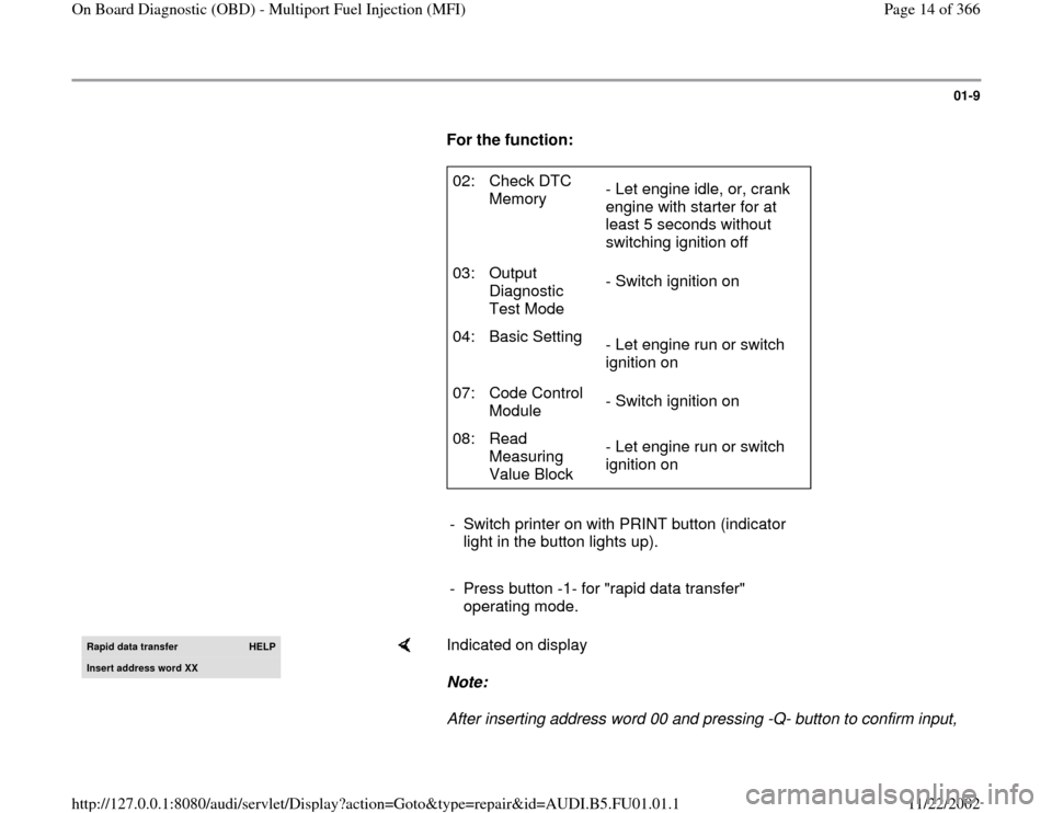
For the function:
02: Check DTC
Memory - Let engine idle, or, crank
engine with starter for at
least 5 seconds without
switching ignition off
03: Output
Diagnostic
Test Mode - Switch ignition on
04: Basic Setting
- Let engine run or switch
ignition on
07: Code Control
Module - Switch ignition on
08: Read
Measuring
Value Block - Let engine run or switch
ignition on
- Switch printer on with PRINT button (indicator
light in the button lights up).
- Press button -1- for "rapid data transfer"
operating mode.
Rapid data transfer
HELP
Insert address word XX
Indicated on display
Note:
After inserting address word 00 and pressing -Q- button to confirm input,
Pa
ge 14 of 366 On Board Dia
gnostic
(OBD
) - Multi
port Fuel In
jection
(MFI
)
11/22/2002 htt
p://127.0.0.1:8080/audi/servlet/Dis
play?action=Goto&t
yp
e=re
pair&id=AUDI.B5.FU01.01.1
Page 198 of 366
01-145
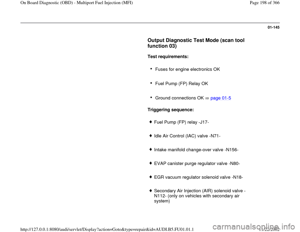
Output Diagnostic Test Mode (scan tool
function 03)
Test requirements:
Fuses for engine electronics OK
Fuel Pump (FP) Relay OK
Ground connections OK page 01
-5
Triggering sequence:
Fuel Pump (FP) relay -J17-
Idle Air Control (IAC) valve -N71-
Intake manifold change-over valve -N156-
EVAP canister purge regulator valve -N80-
EGR vacuum regulator solenoid valve -N18-
Secondary Air Injection (AIR) solenoid valve -
N112- (only on vehicles with secondary air
system)
Pa
ge 198 of 366 On Board Dia
gnostic
(OBD
) - Multi
port Fuel In
jection
(MFI
)
11/22/2002 htt
p://127.0.0.1:8080/audi/servlet/Dis
play?action=Goto&t
yp
e=re
pair&id=AUDI.B5.FU01.01.1
Page 200 of 366
01-146
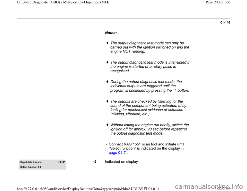
Notes:
The output diagnostic test mode can only be
carried out with the ignition switched on and the
engine NOT running.
The output diagnostic test mode is interrupted if
the engine is started or a rotary pulse is
recognized.
During the output diagnostic test mode, the
individual outputs are triggered until the
program is continued by pressing the button.
The outputs are checked by listening for the
sound of the component being actuated, of by
feeling for mechanical evidence of actuation
(clicking, vibration, etc.).
Without letting the engine run briefly, switch the
ignition off for approx. 20 sec before repeating
the output diagnostic test mode.
- Connect VAG 1551 scan tool and initiate until
"Select function" is indicated on the display
page 01
-7 .
Rapid data transfer
HELP
Select function XX
Indicated on display
Pa
ge 200 of 366 On Board Dia
gnostic
(OBD
) - Multi
port Fuel In
jection
(MFI
)
11/22/2002 htt
p://127.0.0.1:8080/audi/servlet/Dis
play?action=Goto&t
yp
e=re
pair&id=AUDI.B5.FU01.01.1
Page 204 of 366
01-149
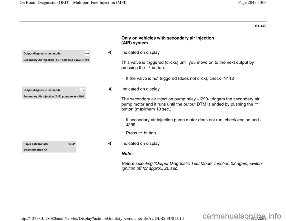
Only on vehicles with secondary air injection
(AIR) system Output diagnostic test mode Secondar
y Air In
jection
(AIR
) solenoid valve -N112
Indicated on display
This valve is triggered (clicks) until you move on to the next output by
pressing the button. - If the valve is not triggered (does not click), check -N112-.
Output diagnostic test mode Secondar
y Air In
jection
(AIR
) pump rela
y -J299
Indicated on display
The secondary air injection pump relay -J299- triggers the secondary air
pump motor and it runs until the output DTM is ended by pushing the
button (maximum 10 sec.). - If secondary air injection pump motor does not run, check engine and -
J299-.
-
Press button.
Rapid data transfer
HELP
Select function XX
Indicated on display
Note:
Before selecting "Output Diagnostic Test Mode" function 03 again, switch
ignition off for approx. 20 sec.
Pa
ge 204 of 366 On Board Dia
gnostic
(OBD
) - Multi
port Fuel In
jection
(MFI
)
11/22/2002 htt
p://127.0.0.1:8080/audi/servlet/Dis
play?action=Goto&t
yp
e=re
pair&id=AUDI.B5.FU01.01.1
Page 245 of 366
01-175
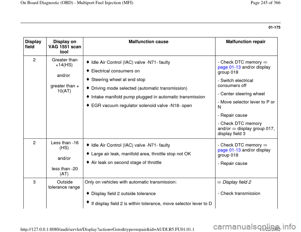
Display
field Display on
VAG 1551 scan
tool Malfunction cause
Malfunction repair
2 Greater than
+14(HS)
and/or
greater than +
10(AT)
Idle Air Control (IAC) valve -N71- faulty
Electrical consumers on
Steering wheel at end stop
Driving mode selected (automatic transmission)
Intake manifold pump plugged in automatic transmission
EGR vacuum regulator solenoid valve -N18- open- Check DTC memory
page 01
-13
and/or display
group 018
- Switch electrical
consumers off
- Center steering wheel
- Move selector lever to P or
N
- Repair cause
- Check DTC memory
and/or display group 017,
display field 3
2 Less than -16
(HS)
and/or
less than -20
(AT)
Idle Air Control (IAC) valve -N71- faulty
Large air leak, manifold area, throttle stop not OK
Air leak on second stage of throttle - Check DTC memory
page 01
-13
and/or display
group 018
- Repair cause
3 Outside
tolerance range Only on vehicles with automatic transmission:
Display field 2 outside tolerance
If display field 2 is within tolerance, move selector lever to D Display field 2
- Check transmission
Pa
ge 245 of 366 On Board Dia
gnostic
(OBD
) - Multi
port Fuel In
jection
(MFI
)
11/22/2002 htt
p://127.0.0.1:8080/audi/servlet/Dis
play?action=Goto&t
yp
e=re
pair&id=AUDI.B5.FU01.01.1
Page 247 of 366
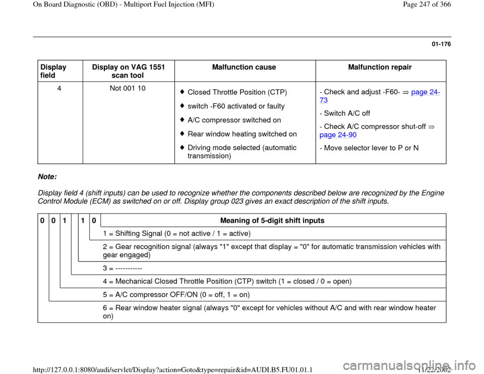
01-176
Display
field Display on VAG 1551
scan tool Malfunction cause
Malfunction repair
4 Not 001 10
Closed Throttle Position (CTP) switch -F60 activated or faulty A/C compressor switched on Rear window heating switched on Driving mode selected (automatic
transmission) - Check and adjust -F60- page 24
-
73
- Switch A/C off
- Check A/C compressor shut-off
page 24
-90
- Move selector lever to P or N
Note:
Display field 4 (shift inputs) can be used to recognize whether the components described below are recognized by the Engine
Control Module (ECM) as switched on or off. Display group 023 gives an exact description of the shift inputs. 0
0
1
1
0
Meaning of 5-digit shift inputs
1 = Shifting Signal (0 = not active / 1 = active)
2 = Gear recognition signal (always "1" except that display = "0" for automatic transmission vehicles with
gear engaged)
3 = -----------
4 = Mechanical Closed Throttle Position (CTP) switch (1 = closed / 0 = open)
5 = A/C compressor OFF/ON (0 = off, 1 = on)
6 = Rear window heater signal (always "0" except for vehicles without A/C and with rear window heater
on)
Pa
ge 247 of 366 On Board Dia
gnostic
(OBD
) - Multi
port Fuel In
jection
(MFI
)
11/22/2002 htt
p://127.0.0.1:8080/audi/servlet/Dis
play?action=Goto&t
yp
e=re
pair&id=AUDI.B5.FU01.01.1
Page 291 of 366
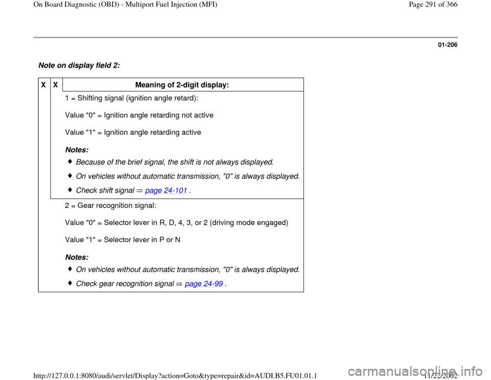
01-206
Note on display field 2: X
X
Meaning of 2-digit display:
1 = Shifting signal (ignition angle retard):
Value "0" = Ignition angle retarding not active
Value "1" = Ignition angle retarding active
Notes:
Because of the brief signal, the shift is not always displayed.
On vehicles without automatic transmission, "0" is always displayed.
Check shift signal page 24
-101
.
2 = Gear recognition signal:
Value "0" = Selector lever in R, D, 4, 3, or 2 (driving mode engaged)
Value "1" = Selector lever in P or N
Notes:
On vehicles without automatic transmission, "0" is always displayed.
Check gear recognition signal page 24
-99
.
Pa
ge 291 of 366 On Board Dia
gnostic
(OBD
) - Multi
port Fuel In
jection
(MFI
)
11/22/2002 htt
p://127.0.0.1:8080/audi/servlet/Dis
play?action=Goto&t
yp
e=re
pair&id=AUDI.B5.FU01.01.1