wiring AUDI A4 1999 B5 / 1.G AHA Engine Multiport Fuel Injection And Ignition System Owner's Guide
[x] Cancel search | Manufacturer: AUDI, Model Year: 1999, Model line: A4, Model: AUDI A4 1999 B5 / 1.GPages: 166, PDF Size: 0.91 MB
Page 105 of 166
24-81
If wiring is OK:
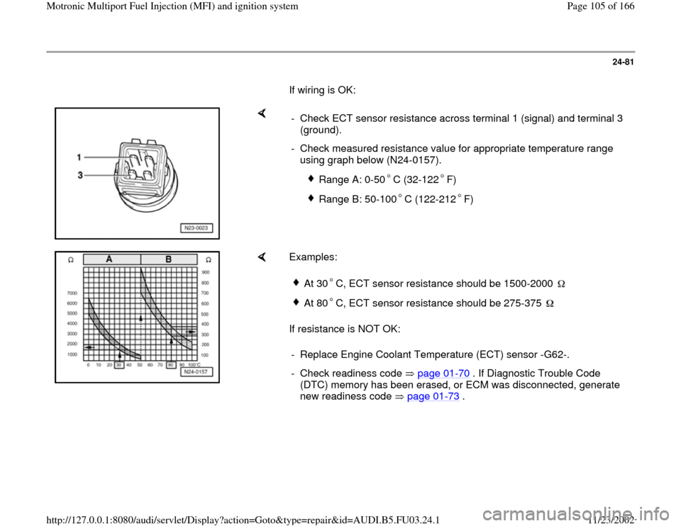
- Check ECT sensor resistance across terminal 1 (signal) and terminal 3
(ground).
- Check measured resistance value for appropriate temperature range
using graph below (N24-0157).
Range A: 0-50 C (32-122 F)
Range B: 50-100 C (122-212 F)
Examples:
If resistance is NOT OK:
At 30 C, ECT sensor resistance should be 1500-2000 At 80 C, ECT sensor resistance should be 275-375
- Replace Engine Coolant Temperature (ECT) sensor -G62-.
- Check readiness code page 01
-70
. If Diagnostic Trouble Code
(DTC) memory has been erased, or ECM was disconnected, generate
new readiness code page 01
-73
.
Pa
ge 105 of 166 Motronic Multi
port Fuel In
jection
(MFI
) and i
gnition s
ystem
11/23/2002 htt
p://127.0.0.1:8080/audi/servlet/Dis
play?action=Goto&t
yp
e=re
pair&id=AUDI.B5.FU03.24.1
Page 106 of 166
24-82
Intake Air Temperature (IAT) sensor,
checking
Required special tools and test equipment
VAG1551 or VAG1552 Scan Tool (ST) with
VAG1551/3 adapter cable
VAG1598/22 test box
Multimeter US1119 (Fluke 83 or equivalent)
VW1594 connector test kit
Wiring diagram
Chilling spray (commercially available)
Pa
ge 106 of 166 Motronic Multi
port Fuel In
jection
(MFI
) and i
gnition s
ystem
11/23/2002 htt
p://127.0.0.1:8080/audi/servlet/Dis
play?action=Goto&t
yp
e=re
pair&id=AUDI.B5.FU03.24.1
Page 108 of 166
24-84
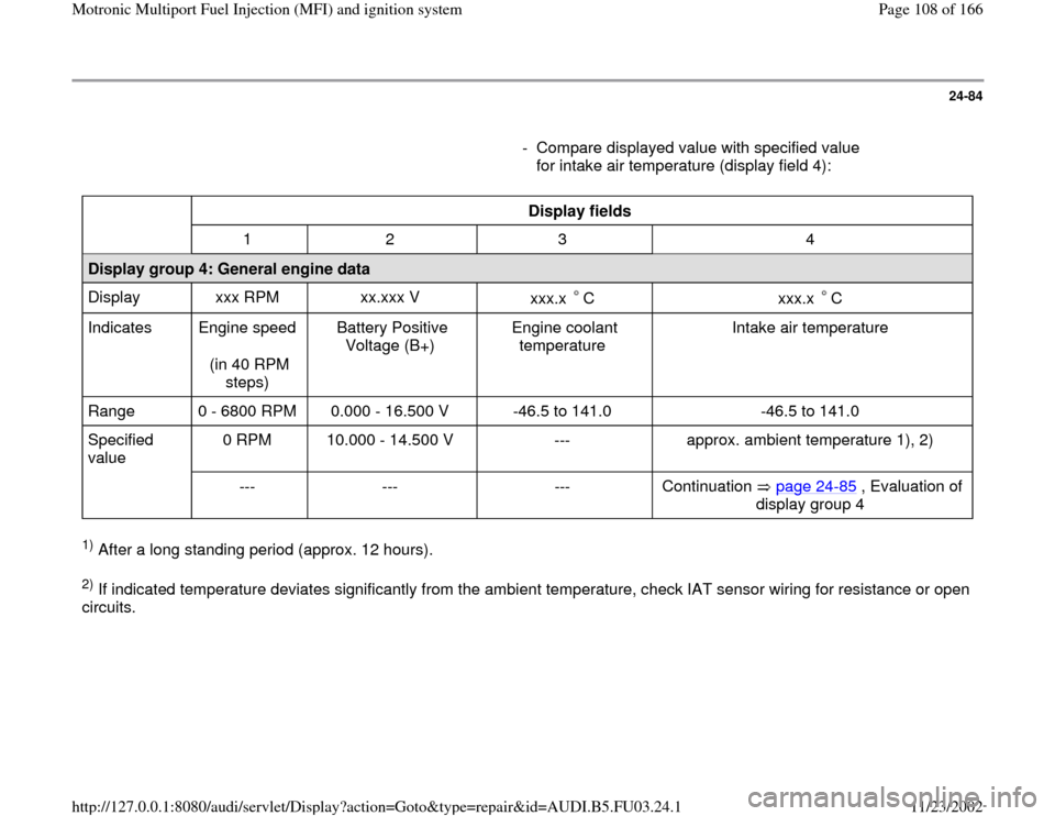
- Compare displayed value with specified value
for intake air temperature (display field 4):
Display fields
1 2 3 4
Display group 4: General engine data
Display xxx RPM xx.xxx V
xxx.x C
xxx.x C
Indicates Engine speed
(in 40 RPM
steps) Battery Positive
Voltage (B+) Engine coolant
temperature Intake air temperature
Range 0 - 6800 RPM 0.000 - 16.500 V -46.5 to 141.0 -46.5 to 141.0
Specified
value 0 RPM 10.000 - 14.500 V --- approx. ambient temperature 1), 2)
--- --- --- Continuation page 24
-85
, Evaluation of
display group 4
1) After a long standing period (approx. 12 hours). 2) If indicated temperature deviates significantly from the ambient temperature, check IAT sensor wiring for resistance or open
circuits.
Pa
ge 108 of 166 Motronic Multi
port Fuel In
jection
(MFI
) and i
gnition s
ystem
11/23/2002 htt
p://127.0.0.1:8080/audi/servlet/Dis
play?action=Goto&t
yp
e=re
pair&id=AUDI.B5.FU03.24.1
Page 109 of 166
24-85
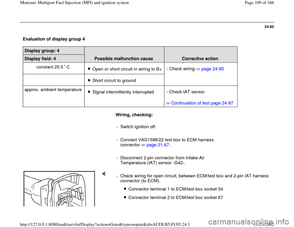
Evaluation of display group 4 Display group: 4
Display field: 4
Possible malfunction cause
Corrective action
constant 25.5 C
Open or short circuit in wiring to B+- Check wiring page 24
-85
Short circuit to ground
approx. ambient temperature Signal intermittently interrupted
Continuation of test page 24
-87
- Check IAT sensor
Wiring, checking:
- Switch ignition off.
- Connect VAG1598/22 test box to ECM harness
connector page 01
-67
.
- Disconnect 2-pin connector from Intake Air
Temperature (IAT) sensor -G42-.
- Check wiring for open circuit, between ECM/test box and 2-pin IAT harness
connector (to ECM).
Connector terminal 1 to ECM/test box socket 54
Connector terminal 2 to ECM/test box socket 67
Pa
ge 109 of 166 Motronic Multi
port Fuel In
jection
(MFI
) and i
gnition s
ystem
11/23/2002 htt
p://127.0.0.1:8080/audi/servlet/Dis
play?action=Goto&t
yp
e=re
pair&id=AUDI.B5.FU03.24.1
Page 111 of 166
24-86
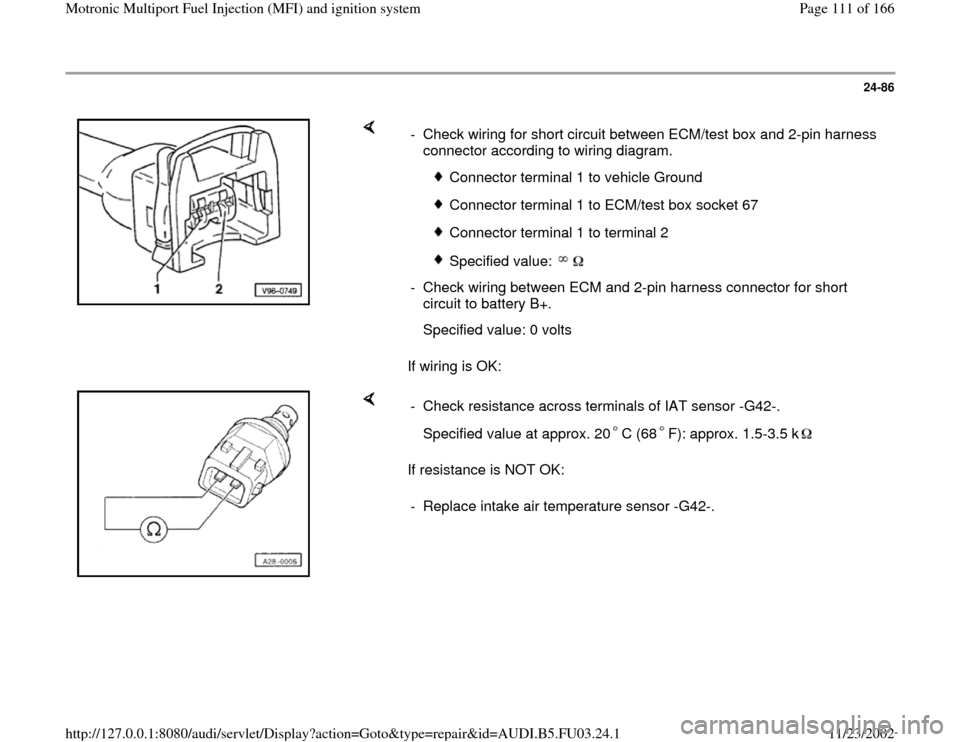
If wiring is OK: - Check wiring for short circuit between ECM/test box and 2-pin harness
connector according to wiring diagram.
Connector terminal 1 to vehicle Ground
Connector terminal 1 to ECM/test box socket 67
Connector terminal 1 to terminal 2
Specified value:
- Check wiring between ECM and 2-pin harness connector for short
circuit to battery B+.
Specified value: 0 volts
If resistance is NOT OK: - Check resistance across terminals of IAT sensor -G42-.
Specified value at approx. 20 C (68 F): approx. 1.5-3.5 k- Replace intake air temperature sensor -G42-.
Pa
ge 111 of 166 Motronic Multi
port Fuel In
jection
(MFI
) and i
gnition s
ystem
11/23/2002 htt
p://127.0.0.1:8080/audi/servlet/Dis
play?action=Goto&t
yp
e=re
pair&id=AUDI.B5.FU03.24.1
Page 113 of 166
24-88
Engine Speed (RPM) sensor, checking
Note:
Component locations page 24
-1
Required special tools and test equipment
VAG1598/22 test box
Multimeter US1119 (Fluke 83 or equivalent)
VW1594 connector test kit
Wiring diagram
Checking
- Disconnect 3-pin harness connector from engine
speed sensor.
- Connect VAG1598/22 test box to ECM harness
connector page 01
-67
.
Pa
ge 113 of 166 Motronic Multi
port Fuel In
jection
(MFI
) and i
gnition s
ystem
11/23/2002 htt
p://127.0.0.1:8080/audi/servlet/Dis
play?action=Goto&t
yp
e=re
pair&id=AUDI.B5.FU03.24.1
Page 114 of 166
24-89
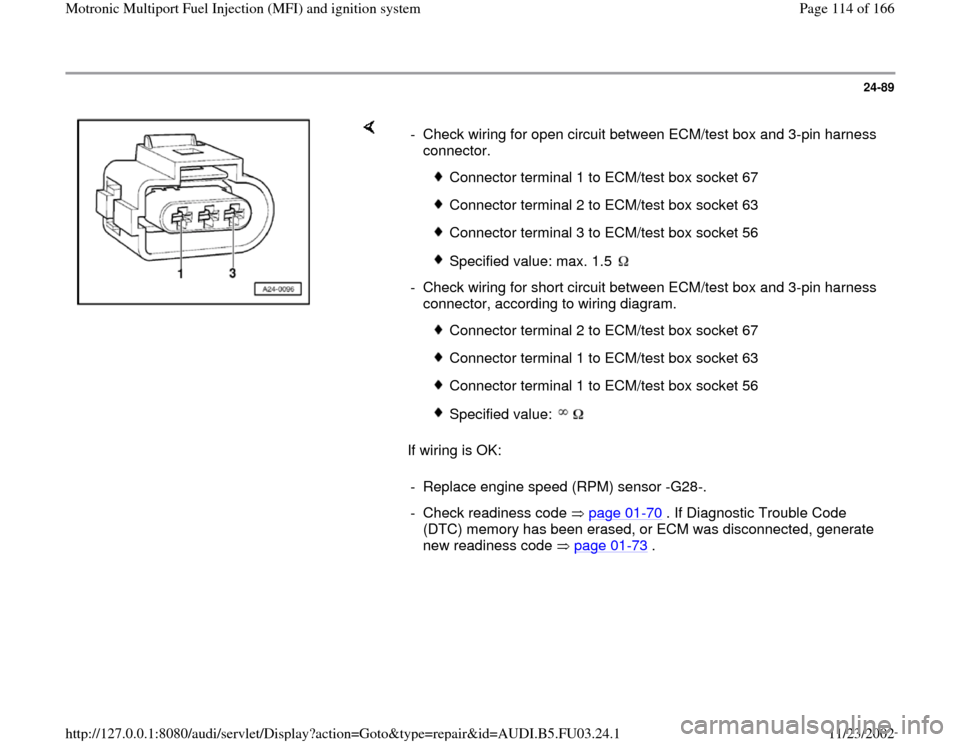
If wiring is OK: - Check wiring for open circuit between ECM/test box and 3-pin harness
connector.
Connector terminal 1 to ECM/test box socket 67
Connector terminal 2 to ECM/test box socket 63
Connector terminal 3 to ECM/test box socket 56
Specified value: max. 1.5
- Check wiring for short circuit between ECM/test box and 3-pin harness
connector, according to wiring diagram.
Connector terminal 2 to ECM/test box socket 67
Connector terminal 1 to ECM/test box socket 63
Connector terminal 1 to ECM/test box socket 56
Specified value:
- Replace engine speed (RPM) sensor -G28-.
- Check readiness code page 01
-70
. If Diagnostic Trouble Code
(DTC) memory has been erased, or ECM was disconnected, generate
new readiness code page 01
-73
.
Pa
ge 114 of 166 Motronic Multi
port Fuel In
jection
(MFI
) and i
gnition s
ystem
11/23/2002 htt
p://127.0.0.1:8080/audi/servlet/Dis
play?action=Goto&t
yp
e=re
pair&id=AUDI.B5.FU03.24.1
Page 115 of 166
24-90
Voltage supply to Engine Control
Module (ECM), checking
Required special tools and test equipment
VAG1551 or VAG1552 Scan Tool (ST) with
VAG1551/3 adapter cable
VAG1598/22 test box
Multimeter US1119 (Fluke 83 or equivalent)
VW1594 connector test kit
Wiring diagram
Checking
- Connect VAG1551 or VAG1552 scan tool and
press buttons -0- and -1- to insert "Engine
Electronics" address word 01 (with ignition
switched on) page 01
-8 .
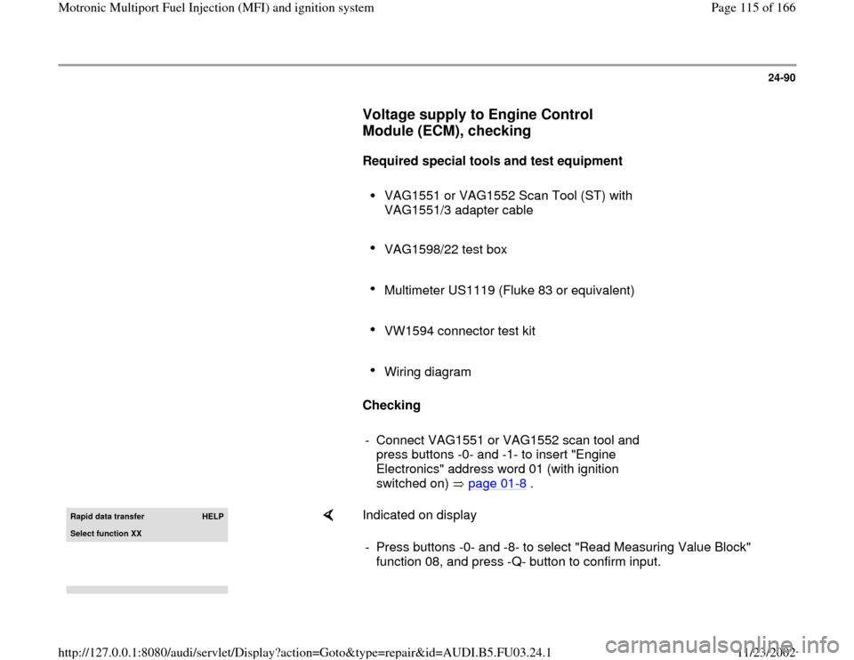
Rapid data transfer
HELP
Select function XX
Indicated on display
- Press buttons -0- and -8- to select "Read Measuring Value Block"
function 08, and press -Q- button to confirm input.
Pa
ge 115 of 166 Motronic Multi
port Fuel In
jection
(MFI
) and i
gnition s
ystem
11/23/2002 htt
p://127.0.0.1:8080/audi/servlet/Dis
play?action=Goto&t
yp
e=re
pair&id=AUDI.B5.FU03.24.1
Page 118 of 166
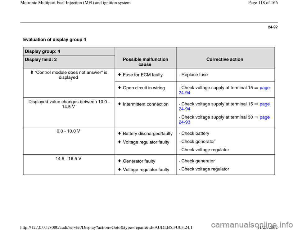
24-92
Evaluation of display group 4 Display group: 4
Display field: 2
Possible malfunction
cause
Corrective action
If "Control module does not answer" is
displayed
Fuse for ECM faulty- Replace fuse
Open circuit in wiring- Check voltage supply at terminal 15 page
24
-94
Displayed value changes between 10.0 -
14.5 V
Intermittent connection- Check voltage supply at terminal 15 page
24
-94
- Check voltage supply at terminal 30 page 24
-93
0.0 - 10.0 V
Battery discharged/faulty Voltage regulator faulty- Check battery
- Check generator
- Check voltage regulator
14.5 - 16.5 V Generator faultyVoltage regulator faulty- Check generator
- Check voltage regulator
Pa
ge 118 of 166 Motronic Multi
port Fuel In
jection
(MFI
) and i
gnition s
ystem
11/23/2002 htt
p://127.0.0.1:8080/audi/servlet/Dis
play?action=Goto&t
yp
e=re
pair&id=AUDI.B5.FU03.24.1
Page 119 of 166
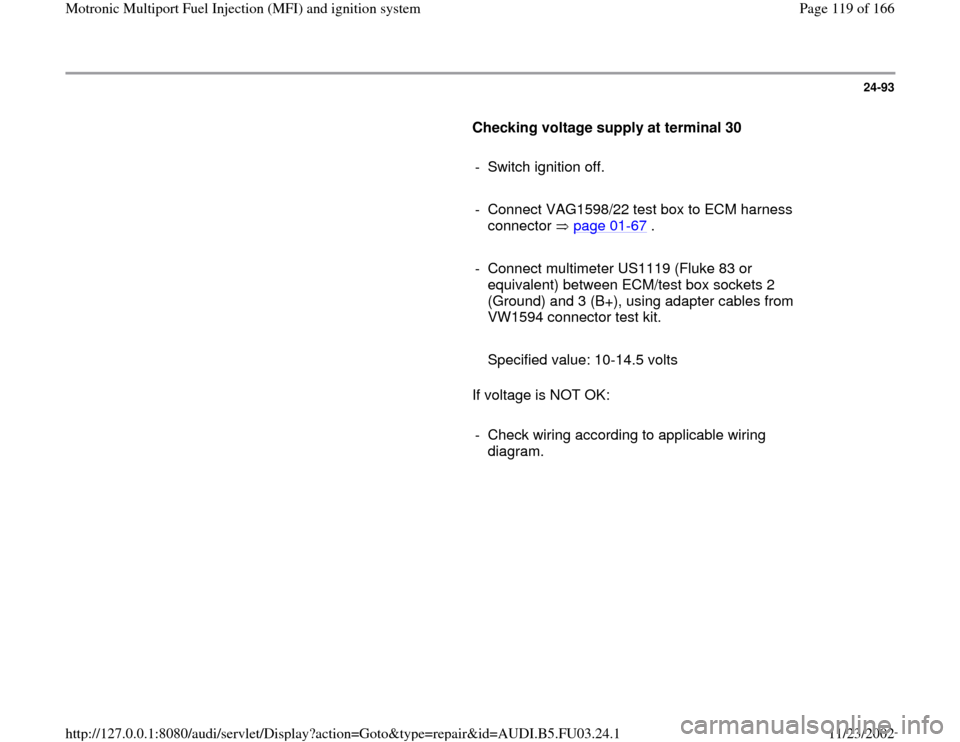
24-93
Checking voltage supply at terminal 30
- Switch ignition off.
- Connect VAG1598/22 test box to ECM harness
connector page 01
-67
.
- Connect multimeter US1119 (Fluke 83 or
equivalent) between ECM/test box sockets 2
(Ground) and 3 (B+), using adapter cables from
VW1594 connector test kit.
Specified value: 10-14.5 volts
If voltage is NOT OK:
- Check wiring according to applicable wiring
diagram.
Pa
ge 119 of 166 Motronic Multi
port Fuel In
jection
(MFI
) and i
gnition s
ystem
11/23/2002 htt
p://127.0.0.1:8080/audi/servlet/Dis
play?action=Goto&t
yp
e=re
pair&id=AUDI.B5.FU03.24.1