wheel bolts AUDI A4 1999 B5 / 1.G APB Engine Cylinder Block Crankshaft And Flywheel Assembly Manual
[x] Cancel search | Manufacturer: AUDI, Model Year: 1999, Model line: A4, Model: AUDI A4 1999 B5 / 1.GPages: 26, PDF Size: 0.41 MB
Page 3 of 26
13-16
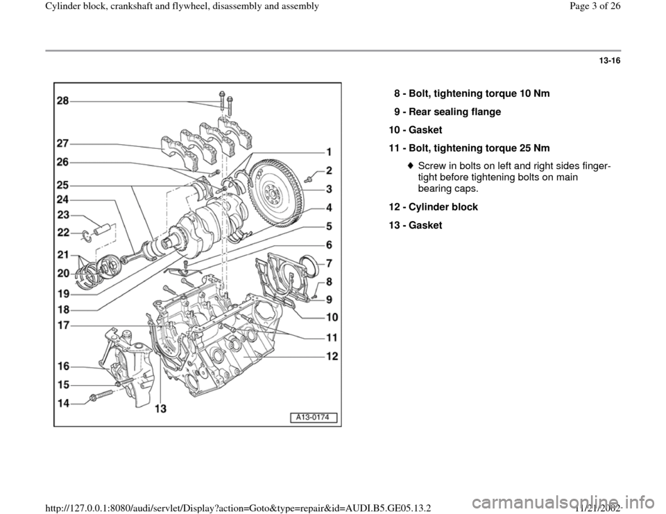
8 -
Bolt, tightening torque 10 Nm
9 -
Rear sealing flange
10 -
Gasket
11 -
Bolt, tightening torque 25 Nm
Screw in bolts on left and right sides finger-
tight before tightening bolts on main
bearing caps.
12 -
Cylinder block
13 -
Gasket
Pa
ge 3 of 26 C
ylinder block, crankshaft and fl
ywheel, disassembl
y and assembl
y
11/21/2002 htt
p://127.0.0.1:8080/audi/servlet/Dis
play?action=Goto&t
yp
e=re
pair&id=AUDI.B5.GE05.13.2
Page 6 of 26
13-19
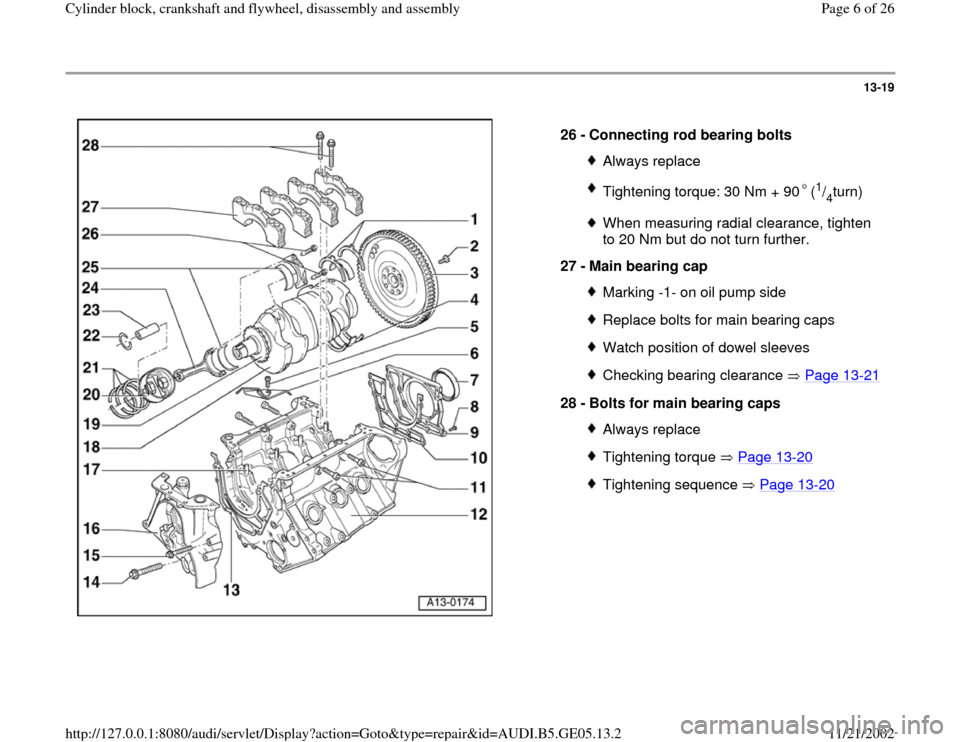
26 -
Connecting rod bearing bolts
Always replaceTightening torque: 30 Nm + 90 (
1/4turn)
When measuring radial clearance, tighten
to 20 Nm but do not turn further.
27 -
Main bearing cap Marking -1- on oil pump sideReplace bolts for main bearing capsWatch position of dowel sleevesChecking bearing clearance Page 13
-21
28 -
Bolts for main bearing caps
Always replaceTightening torque Page 13
-20
Tightening sequence Page 13
-20Pa
ge 6 of 26 C
ylinder block, crankshaft and fl
ywheel, disassembl
y and assembl
y
11/21/2002 htt
p://127.0.0.1:8080/audi/servlet/Dis
play?action=Goto&t
yp
e=re
pair&id=AUDI.B5.GE05.13.2
Page 7 of 26
13-20
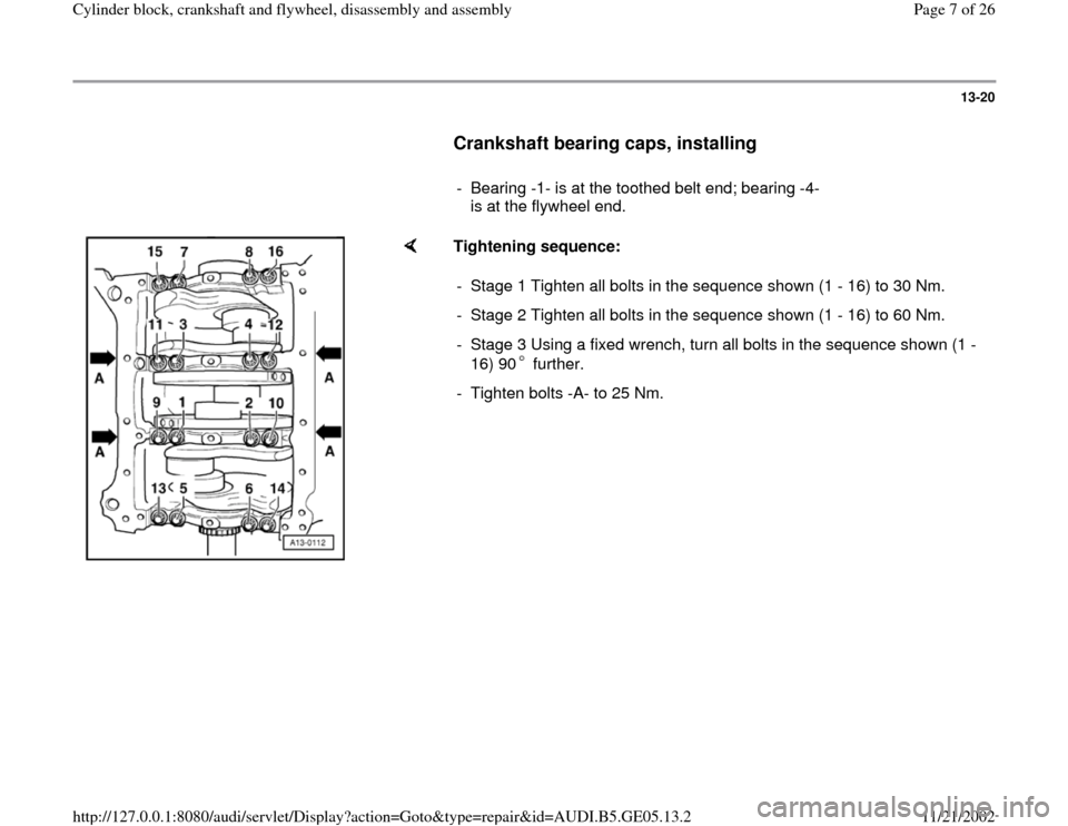
Crankshaft bearing caps, installing
- Bearing -1- is at the toothed belt end; bearing -4-
is at the flywheel end.
Tightening sequence:
- Stage 1 Tighten all bolts in the sequence shown (1 - 16) to 30 Nm.
- Stage 2 Tighten all bolts in the sequence shown (1 - 16) to 60 Nm.
- Stage 3 Using a fixed wrench, turn all bolts in the sequence shown (1 -
16) 90 further. - Tighten bolts -A- to 25 Nm.
Pa
ge 7 of 26 C
ylinder block, crankshaft and fl
ywheel, disassembl
y and assembl
y
11/21/2002 htt
p://127.0.0.1:8080/audi/servlet/Dis
play?action=Goto&t
yp
e=re
pair&id=AUDI.B5.GE05.13.2
Page 12 of 26
13-25
Installing
- Install sealing flange.
- Install dual-mass flywheel with new bolts.
Note:
Always replace securing bolts for dual-mass
flywheel.
- Install clutch.
Repair Manual, 6 Spd. Manual Transmission
01E, Repair Group 30
Tightening torques
Dual-mass flywheel to
crankshaft 60 Nm + 180
Clutch to dual-mass flywheel 20 Nm
Pa
ge 12 of 26 C
ylinder block, crankshaft and fl
ywheel, disassembl
y and assembl
y
11/21/2002 htt
p://127.0.0.1:8080/audi/servlet/Dis
play?action=Goto&t
yp
e=re
pair&id=AUDI.B5.GE05.13.2
Page 14 of 26
13-27
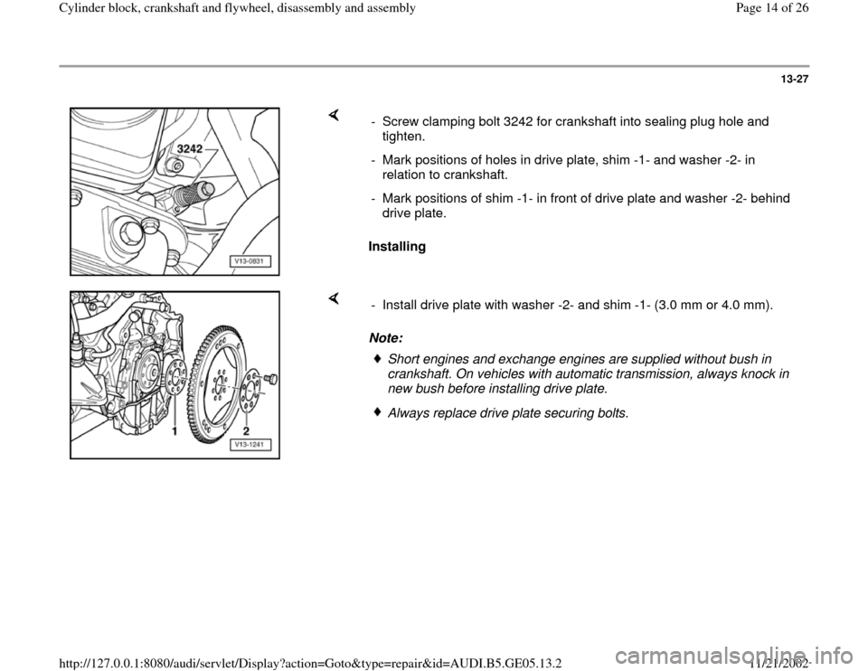
Installing - Screw clamping bolt 3242 for crankshaft into sealing plug hole and
tighten.
- Mark positions of holes in drive plate, shim -1- and washer -2- in
relation to crankshaft.
- Mark positions of shim -1- in front of drive plate and washer -2- behind
drive plate.
Note: - Install drive plate with washer -2- and shim -1- (3.0 mm or 4.0 mm).
Short engines and exchange engines are supplied without bush in
crankshaft. On vehicles with automatic transmission, always knock in
new bush before installing drive plate. Always replace drive plate securing bolts.
Pa
ge 14 of 26 C
ylinder block, crankshaft and fl
ywheel, disassembl
y and assembl
y
11/21/2002 htt
p://127.0.0.1:8080/audi/servlet/Dis
play?action=Goto&t
yp
e=re
pair&id=AUDI.B5.GE05.13.2
Page 15 of 26
13-28
Tightening torques
Drive plate to crankshaft
60 Nm + 90
Note:
Always replace securing bolts for drive plate.
Note:
Before installing the transmission, check that the dowel sleeves for
locating engine/transmission are fitted in the engine flange.
Repair Manual, 5 Spd. Automatic Transmission 01V, Repair Group 37
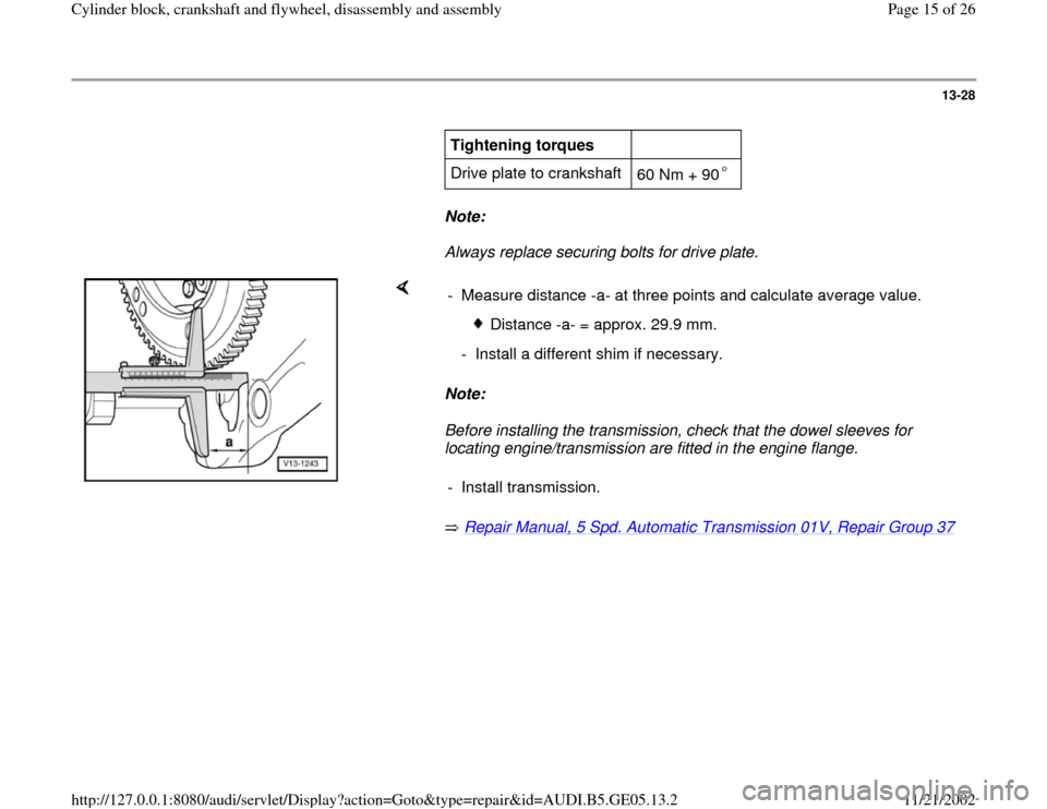
- Measure distance -a- at three points and calculate average value.
Distance -a- = approx. 29.9 mm.
- Install a different shim if necessary.
- Install transmission.
Pa
ge 15 of 26 C
ylinder block, crankshaft and fl
ywheel, disassembl
y and assembl
y
11/21/2002 htt
p://127.0.0.1:8080/audi/servlet/Dis
play?action=Goto&t
yp
e=re
pair&id=AUDI.B5.GE05.13.2
Page 16 of 26
13-29
Dual-mass flywheel / drive plate,
installation dimensions, removing and
installing
A - Flywheel
Removing
- Remove transmission.
Repair Manual, 6 Spd. Manual Transmission
01V, Repair Group 34
- Remove clutch.
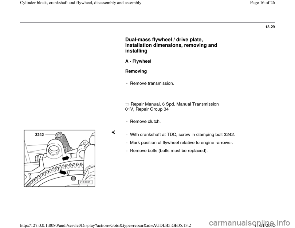
- With crankshaft at TDC, screw in clamping bolt 3242.
- Mark position of flywheel relative to engine -arrows-.
- Remove bolts (bolts must be replaced).
Pa
ge 16 of 26 C
ylinder block, crankshaft and fl
ywheel, disassembl
y and assembl
y
11/21/2002 htt
p://127.0.0.1:8080/audi/servlet/Dis
play?action=Goto&t
yp
e=re
pair&id=AUDI.B5.GE05.13.2
Page 17 of 26
13-30
Note:
The needle bearing is located in the flywheel and
must be pressed in if a new flywheel is installed
Page 13
-35
.
Installing
- Install dual-mass flywheel.
Note:
Always replace flywheel securing bolts.
- Install clutch.
Repair Manual, 6 Spd. Manual Transmission
01E, Repair Group 30
- Install transmission.
Repair Manual, 6 Spd. Manual Transmission
01E, Repair Group 34
Pa
ge 17 of 26 C
ylinder block, crankshaft and fl
ywheel, disassembl
y and assembl
y
11/21/2002 htt
p://127.0.0.1:8080/audi/servlet/Dis
play?action=Goto&t
yp
e=re
pair&id=AUDI.B5.GE05.13.2
Page 20 of 26
13-33
Installing
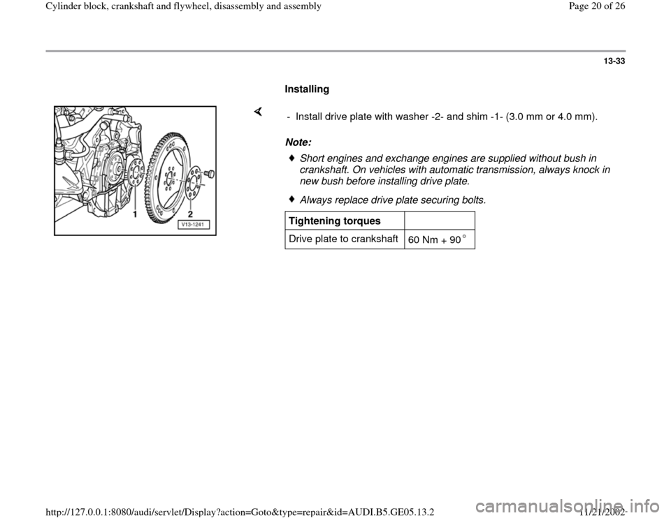
Note: - Install drive plate with washer -2- and shim -1- (3.0 mm or 4.0 mm).
Short engines and exchange engines are supplied without bush in
crankshaft. On vehicles with automatic transmission, always knock in
new bush before installing drive plate. Always replace drive plate securing bolts.
Tightening torques
Drive plate to crankshaft
60 Nm + 90
Pa
ge 20 of 26 C
ylinder block, crankshaft and fl
ywheel, disassembl
y and assembl
y
11/21/2002 htt
p://127.0.0.1:8080/audi/servlet/Dis
play?action=Goto&t
yp
e=re
pair&id=AUDI.B5.GE05.13.2
Page 26 of 26
13-39
Connecting rods and connecting rod
bearings, installing
Note:
Only replace complete sets of connecting
rods
Do not interchange connecting rod bearings.
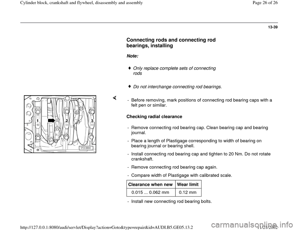
Checking radial clearance - Before removing, mark positions of connecting rod bearing caps with a
felt pen or similar.
- Remove connecting rod bearing cap. Clean bearing cap and bearing
journal.
- Place a length of Plastigage corresponding to width of bearing on
bearing journal or bearing shell.
- Install connecting rod bearing cap and tighten to 20 Nm. Do not rotate
crankshaft.
- Remove connecting rod bearing cap again.
- Compare width of Plastigage with calibrated scale.Clearance when new
Wear limit
0.015 ... 0.062 mm 0.12 mm - Install new connecting rod bearing bolts.
Pa
ge 26 of 26 C
ylinder block, crankshaft and fl
ywheel, disassembl
y and assembl
y
11/21/2002 htt
p://127.0.0.1:8080/audi/servlet/Dis
play?action=Goto&t
yp
e=re
pair&id=AUDI.B5.GE05.13.2