sensor AUDI A4 1999 B5 / 1.G APB Engine Ignition System Checking
[x] Cancel search | Manufacturer: AUDI, Model Year: 1999, Model line: A4, Model: AUDI A4 1999 B5 / 1.GPages: 64, PDF Size: 0.37 MB
Page 19 of 64
28-17
Intake Air Temperature (IAT) sensor -
G42, checking
Location of sensor and connector Page 24
-5 .
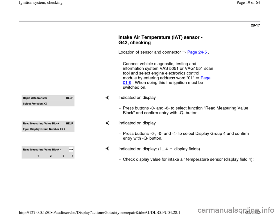
- Connect vehicle diagnostic, testing and
information system VAS 5051 or VAG1551 scan
tool and select engine electronics control
module by entering address word "01" Page
01
-9 . When doing this the ignition must be
switched on.
Rapid data transfer
HELP
Select Function XX
Indicated on display
- Press buttons -0- and -8- to select function "Read Measuring Value
Block" and confirm entry with -Q- button.
Read Measurin
g Value Block
HELP
Input Displa
y Group Number XXX
Indicated on display
- Press buttons -0-, -0- and -4- to select Display Group 4 and confirm
entry with -Q- button.
Read Measuring Value Block 4
1
2
3
4
Indicated on display: (1...4 display fields) - Check display value for intake air temperature sensor (display field 4):
Pa
ge 19 of 64 I
gnition s
ystem, checkin
g
11/22/2002 htt
p://127.0.0.1:8080/audi/servlet/Dis
play?action=Goto&t
yp
e=re
pair&id=AUDI.B5.FU04.28.1
Page 20 of 64
28-18
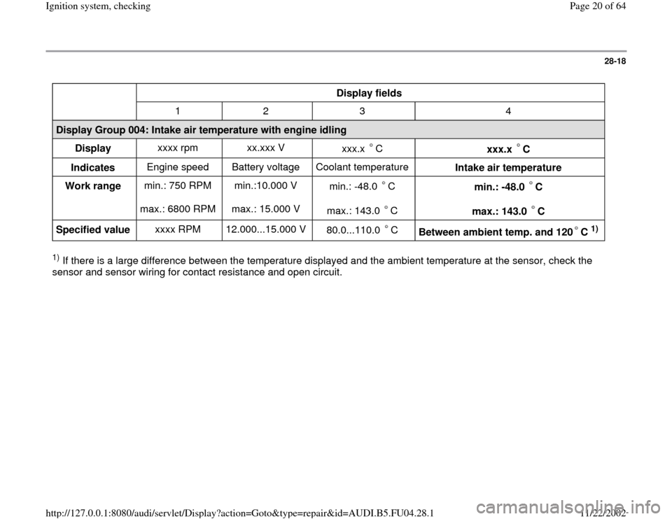
Display fields
1 2 3 4
Display Group 004: Intake air temperature with engine idling
Display xxxx rpm xx.xxx V
xxx.x C
xxx.x C
Indicates Engine speed Battery voltage Coolant temperature
Intake air temperature
Work range min.: 750 RPM
max.: 6800 RPM min.:10.000 V
max.: 15.000 V min.: -48.0 C
max.: 143.0 C
min.: -48.0 C
max.: 143.0 C
Specified value xxxx RPM 12.000...15.000 V
80.0...110.0 C
Between ambient temp. and 120 C
1)
1) If there is a large difference between the temperature displayed and the ambient temperature at the sensor, check the
sensor and sensor wiring for contact resistance and open circuit.
Pa
ge 20 of 64 I
gnition s
ystem, checkin
g
11/22/2002 htt
p://127.0.0.1:8080/audi/servlet/Dis
play?action=Goto&t
yp
e=re
pair&id=AUDI.B5.FU04.28.1
Page 22 of 64
28-20
If no malfunction in wire is detected:
Checking sender
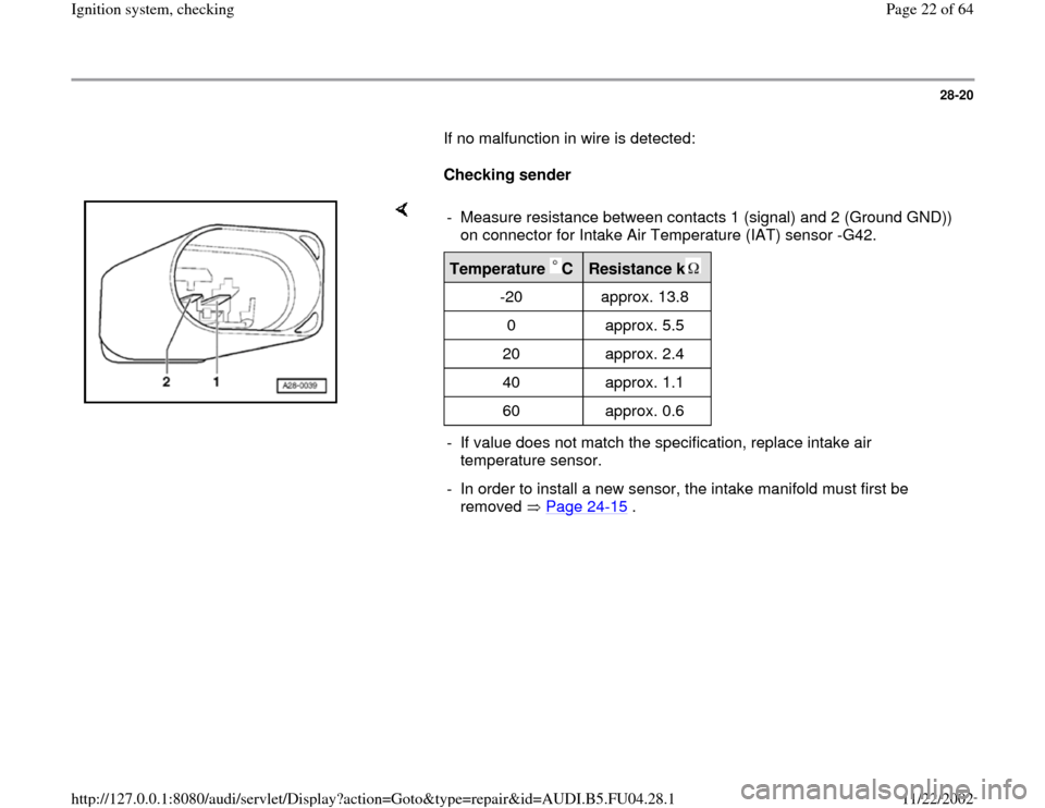
- Measure resistance between contacts 1 (signal) and 2 (Ground GND))
on connector for Intake Air Temperature (IAT) sensor -G42. Temperature C
Resistance k
-20 approx. 13.8
0 approx. 5.5
20 approx. 2.4
40 approx. 1.1
60 approx. 0.6
- If value does not match the specification, replace intake air
temperature sensor.
- In order to install a new sensor, the intake manifold must first be
removed Page 24
-15
.
Pa
ge 22 of 64 I
gnition s
ystem, checkin
g
11/22/2002 htt
p://127.0.0.1:8080/audi/servlet/Dis
play?action=Goto&t
yp
e=re
pair&id=AUDI.B5.FU04.28.1
Page 23 of 64
28-21
Engine Speed (RPM) sensor -G28,
checking
Note:
The engine speed sender is a combined speed
sender and reference mark sender. Without a
signal from the Engine Speed (RPM) sensor -
G28 the engine cannot be started. If the signal
from the Engine Speed (RPM) sensor -G28 fails
while the engine is running, the engine will cut
out immediately.
Checking Engine Speed (RPM) sensor
Component location of sensor and connector
Page 24
-5 .
- Before carrying out test, make sure that sensor
is correctly installed and firmly seated.
- Disconnect harness connector for Engine Speed
(RPM) sensor (grey connector).
Pa
ge 23 of 64 I
gnition s
ystem, checkin
g
11/22/2002 htt
p://127.0.0.1:8080/audi/servlet/Dis
play?action=Goto&t
yp
e=re
pair&id=AUDI.B5.FU04.28.1
Page 24 of 64
28-22
Notes:
If the specification is not attained:
If the specification is attained:
If the specification is not attained:
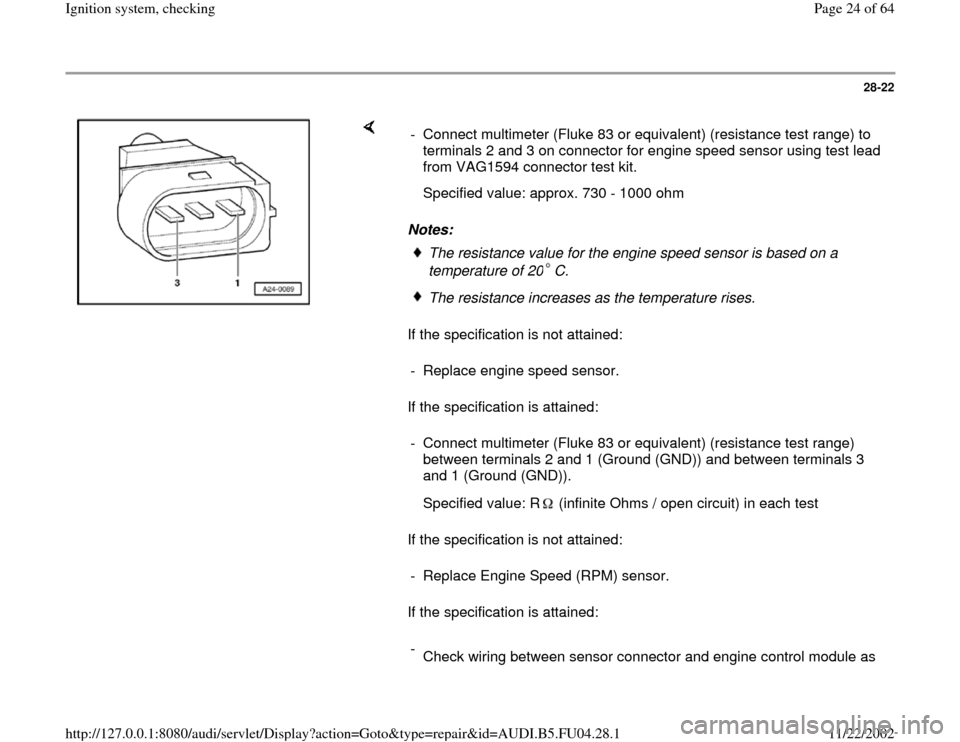
If the specification is attained: - Connect multimeter (Fluke 83 or equivalent) (resistance test range) to
terminals 2 and 3 on connector for engine speed sensor using test lead
from VAG1594 connector test kit.
Specified value: approx. 730 - 1000 ohm
The resistance value for the engine speed sensor is based on a
temperature of 20 C. The resistance increases as the temperature rises.
- Replace engine speed sensor.
- Connect multimeter (Fluke 83 or equivalent) (resistance test range)
between terminals 2 and 1 (Ground (GND)) and between terminals 3
and 1 (Ground (GND)).
Specified value: R (infinite Ohms / open circuit) in each test
- Replace Engine Speed (RPM) sensor.
-
Check wiring between sensor connector and engine control module as
Pa
ge 24 of 64 I
gnition s
ystem, checkin
g
11/22/2002 htt
p://127.0.0.1:8080/audi/servlet/Dis
play?action=Goto&t
yp
e=re
pair&id=AUDI.B5.FU04.28.1
Page 27 of 64
28-24
If the values are not as specified:
- Rectify short or open circuit in wiring between
sender connector and control module connector.
Terminal on sensor
connector
Terminal on control
module connector
1
2
3 108
90
82
- If no open circuits or short circuits are identified,
replace Engine Control Module (ECM) Page
24
-24
.
Pa
ge 27 of 64 I
gnition s
ystem, checkin
g
11/22/2002 htt
p://127.0.0.1:8080/audi/servlet/Dis
play?action=Goto&t
yp
e=re
pair&id=AUDI.B5.FU04.28.1
Page 28 of 64
28-25
Engine Coolant Temperature (ECT)
sensor -G62, checking
Note:
Component location of coolant temperature
sensor Page 24
-5 .
Test conditions
Engine cold
- Connect vehicle diagnostic, testing and
information system VAS 5051 or VAG1551 scan
tool to vehicle and select engine electronics
control module by entering address word "01"
Page 01
-9 .
When doing this the engine must be at idle.
Pa
ge 28 of 64 I
gnition s
ystem, checkin
g
11/22/2002 htt
p://127.0.0.1:8080/audi/servlet/Dis
play?action=Goto&t
yp
e=re
pair&id=AUDI.B5.FU04.28.1
Page 31 of 64
28-28
If display field 3 does not display a realistic
value:
- Disconnect harness connector from coolant
temperature sensor.
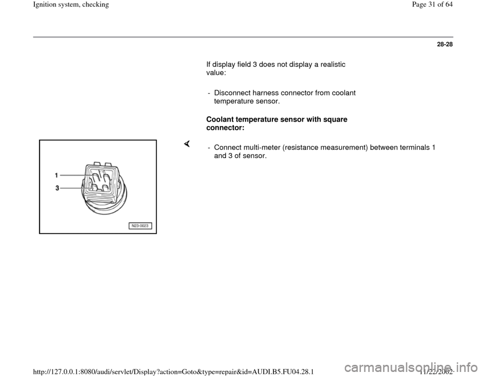
Coolant temperature sensor with square
connector:
- Connect multi-meter (resistance measurement) between terminals 1
and 3 of sensor.
Pa
ge 31 of 64 I
gnition s
ystem, checkin
g
11/22/2002 htt
p://127.0.0.1:8080/audi/servlet/Dis
play?action=Goto&t
yp
e=re
pair&id=AUDI.B5.FU04.28.1
Page 32 of 64
28-29
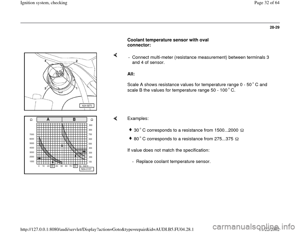
Coolant temperature sensor with oval
connector:
All:
Scale A shows resistance values for temperature range 0 - 50 C and
scale B the values for temperature range 50 - 100 C. - Connect multi-meter (resistance measurement) between terminals 3
and 4 of sensor.
Examples:
If value does not match the specification:
30 C corresponds to a resistance from 1500...2000 80 C corresponds to a resistance from 275...375
- Replace coolant temperature sensor.
Pa
ge 32 of 64 I
gnition s
ystem, checkin
g
11/22/2002 htt
p://127.0.0.1:8080/audi/servlet/Dis
play?action=Goto&t
yp
e=re
pair&id=AUDI.B5.FU04.28.1
Page 33 of 64
28-30
If the value does match the specification:
- Connect test box VAG1598/31 to wiring harness
for engine control module. Do not connect to the
engine control module itself. Page 24
-20
.
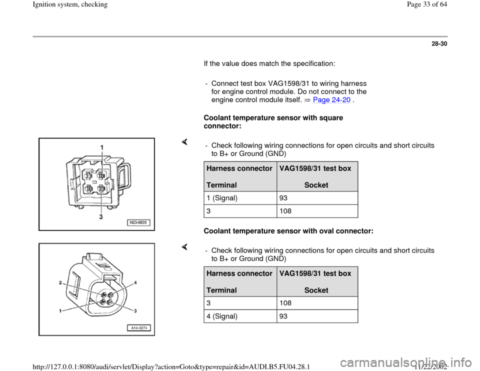
Coolant temperature sensor with square
connector:
Coolant temperature sensor with oval connector: - Check following wiring connections for open circuits and short circuits
to B+ or Ground (GND) Harness connector
Terminal
VAG1598/31 test box
Socket
1 (Signal) 93
3 108
- Check following wiring connections for open circuits and short circuits
to B+ or Ground (GND) Harness connector
Terminal
VAG1598/31 test box
Socket
3 108
4 (Signal) 93
Pa
ge 33 of 64 I
gnition s
ystem, checkin
g
11/22/2002 htt
p://127.0.0.1:8080/audi/servlet/Dis
play?action=Goto&t
yp
e=re
pair&id=AUDI.B5.FU04.28.1