display AUDI A4 1999 B5 / 1.G APB Engine Motronic Multiport Fuel Injection System Servising Workshop Manual
[x] Cancel search | Manufacturer: AUDI, Model Year: 1999, Model line: A4, Model: AUDI A4 1999 B5 / 1.GPages: 90, PDF Size: 0.84 MB
Page 27 of 90
24-24
Motronic Engine Control Module (ECM) -
J220, replacing
Note:
When the engine control module is disconnected
the learned values are erased but the contents of
the DTC memory remain intact.
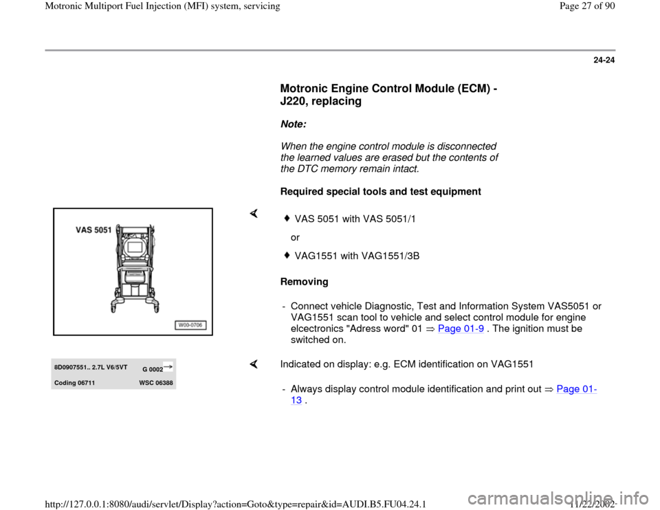
Required special tools and test equipment
Removing
VAS 5051 with VAS 5051/1
orVAG1551 with VAG1551/3B
- Connect vehicle Diagnostic, Test and Information System VAS5051 or
VAG1551 scan tool to vehicle and select control module for engine
elcectronics "Adress word" 01 Page 01
-9 . The ignition must be
switched on.
8D0907551.. 2.7L V6/5VT
G 0002
Codin
g 06711
WSC 06388
Indicated on display: e.g. ECM identification on VAG1551
- Always display control module identification and print out Page 01
-
13
.
Pa
ge 27 of 90 Motronic Multi
port Fuel In
jection
(MFI
) system, servicin
g
11/22/2002 htt
p://127.0.0.1:8080/audi/servlet/Dis
play?action=Goto&t
yp
e=re
pair&id=AUDI.B5.FU04.24.1
Page 33 of 90
24-28
- Check DTC memory Page 01
-15
. The DTC
memory must be clear. If necessary, repair any
malfunctions and erase the DTC memory.
Switch off the engine, then start up again. Take
vehicle for a test drive and check DTC memory
again to make sure it is clear.
- Run engine at idle speed.
CAUTION!
The electric radiator fan should not be
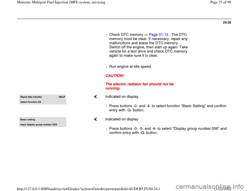
running. Rapid data transfer
HELP
Select function XX
Indicated on display
- Press buttons -0- and -4- to select function "Basic Setting" and confirm
entry with -Q- button.
Basic settin
g
Input displa
y group number XXX
Indicated on display
- Press buttons -0- -5- and -6- to select "Display group number 056" and
confirm entry with -Q- button.
Pa
ge 33 of 90 Motronic Multi
port Fuel In
jection
(MFI
) system, servicin
g
11/22/2002 htt
p://127.0.0.1:8080/audi/servlet/Dis
play?action=Goto&t
yp
e=re
pair&id=AUDI.B5.FU04.24.1
Page 34 of 90
24-29
Notes:
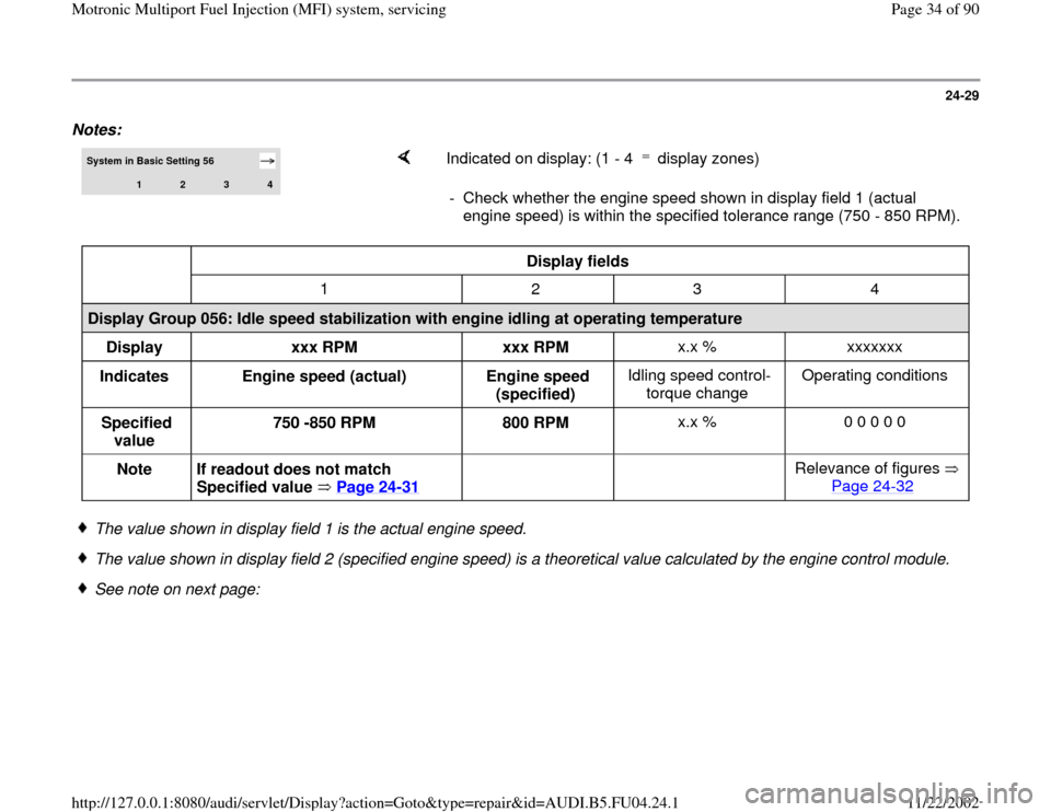
System in Basic Setting 56
1
2
3
4
Indicated on display: (1 - 4 display zones) - Check whether the engine speed shown in display field 1 (actual
engine speed) is within the specified tolerance range (750 - 850 RPM).
Display fields
1 2 3 4
Display Group 056: Idle speed stabilization with engine idling at operating temperature
Display
xxx RPM
xxx RPM x.x % xxxxxxx
Indicates
Engine speed (actual)
Engine speed
(specified) Idling speed control-
torque change Operating conditions
Specified
value 750 -850 RPM
800 RPM x.x % 0 0 0 0 0
Note
If readout does not match
Specified value Page 24
-31
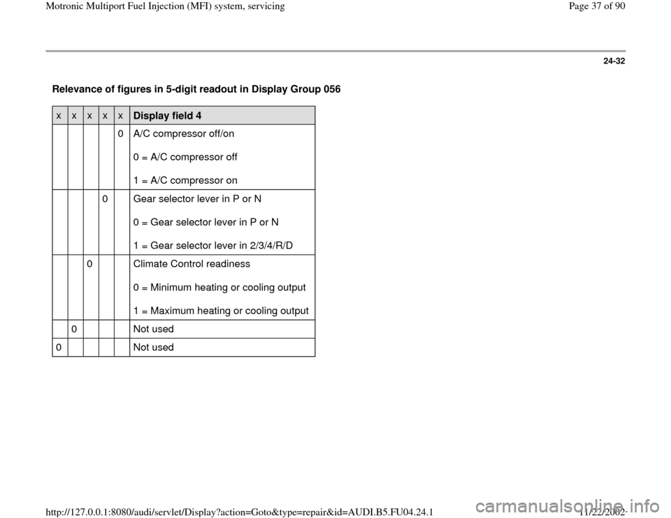
Relevance of figures
Page 24
-32
The value shown in display field 1 is the actual engine speed.
The value shown in display field 2 (specified engine speed) is a theoretical value calculated by the engine control module.
See note on next page:
Pa
ge 34 of 90 Motronic Multi
port Fuel In
jection
(MFI
) system, servicin
g
11/22/2002 htt
p://127.0.0.1:8080/audi/servlet/Dis
play?action=Goto&t
yp
e=re
pair&id=AUDI.B5.FU04.24.1
Page 35 of 90
24-30
When the engine is idling the engine control
module tries constantly to adjust the actual
engine speed so that it matches the specified
value.
This means that the actual engine speed when
idling should always be approximately the same
as the specified engine speed.
Display fields 3 and 4 provide additional
information which is not relevant when checking
the idle speed.
-
Press button.
- Press buttons -0- and -6- to select function "End
Output" and confirm entry with -Q- button.
- If readout does not match Specified value, check
DTC memory again.
- If DTC memory was erased, generate readiness
code Page 01
-105
.
Pa
ge 35 of 90 Motronic Multi
port Fuel In
jection
(MFI
) system, servicin
g
11/22/2002 htt
p://127.0.0.1:8080/audi/servlet/Dis
play?action=Goto&t
yp
e=re
pair&id=AUDI.B5.FU04.24.1
Page 37 of 90
24-32
Relevance of figures in 5-digit readout in Display Group 056 x
x
x
x
x
Display field 4
0 A/C compressor off/on
0 = A/C compressor off
1 = A/C compressor on
0 Gear selector lever in P or N
0 = Gear selector lever in P or N
1 = Gear selector lever in 2/3/4/R/D
0 Climate Control readiness
0 = Minimum heating or cooling output
1 = Maximum heating or cooling output
0 Not used
0 Not used
Pa
ge 37 of 90 Motronic Multi
port Fuel In
jection
(MFI
) system, servicin
g
11/22/2002 htt
p://127.0.0.1:8080/audi/servlet/Dis
play?action=Goto&t
yp
e=re
pair&id=AUDI.B5.FU04.24.1
Page 70 of 90
24-60
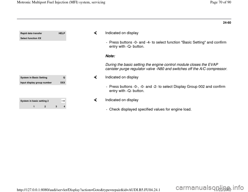
Rapid data transfer
HELP
Select function XX
Indicated on display
Note:
During the basic setting the engine control module closes the EVAP
canister purge regulator valve -N80 and switches off the A/C compressor. - Press buttons -0- and -4- to select function "Basic Setting" and confirm
entry with -Q- button.
System in Basic Settin
g
Q
Input displa
y group number
XXX
Indicated on display
- Press buttons -0-, -0- and -2- to select Display Group 002 and confirm
entry with -Q- button.
System in basic setting 2
1
2
3
4
Indicated on display
- Check displayed specified values for engine load.
Pa
ge 70 of 90 Motronic Multi
port Fuel In
jection
(MFI
) system, servicin
g
11/22/2002 htt
p://127.0.0.1:8080/audi/servlet/Dis
play?action=Goto&t
yp
e=re
pair&id=AUDI.B5.FU04.24.1
Page 71 of 90
24-61
Note:
Read measuring value block display group 2 as
described in repair manual and evaluate it
Page 24
-69
. If the suggested repair steps refer
to the voltage supply test for the Mass Air Flow
(MAF) sensor or the wiring connections from the
Mass Air Flow (MAF) sensor to the Engine
Control Module (ECM), proceed to the following
pages.
Please note the distinction between sensors
made by Bosch and those made by Hitachi
(recognizable via the writing on the sensor).
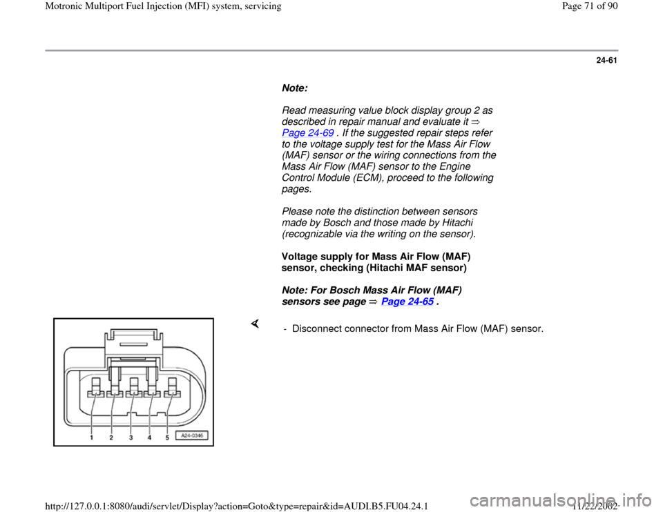
Voltage supply for Mass Air Flow (MAF)
sensor, checking (Hitachi MAF sensor)
Note: For Bosch Mass Air Flow (MAF)
sensors see page Page 24
-65
.
- Disconnect connector from Mass Air Flow (MAF) sensor.
Pa
ge 71 of 90 Motronic Multi
port Fuel In
jection
(MFI
) system, servicin
g
11/22/2002 htt
p://127.0.0.1:8080/audi/servlet/Dis
play?action=Goto&t
yp
e=re
pair&id=AUDI.B5.FU04.24.1
Page 79 of 90
24-69
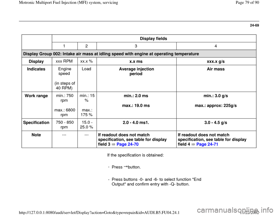
Display fields
1 2 3 4
Display Group 002: Intake air mass at idling speed with engine at operating temperature
Display xxx RPM xx.x %
x.x ms
xxx.x g/s
Indicates Engine
speed
(in steps of
40 RPM) Load
Average injection
period Air mass
Work range min.: 750
rpm
max.: 6800
rpm min.: 15
%
max.:
175 % min.: 2.0 ms
max.: 19.0 ms min.: 3.0 g/s
max.: approx: 225g/s
Specification 750 - 850
rpm 15.0 -
25.0 % 2.0 - 4.0 ms1.
3.0 - 4.5 g/s
Note --- ---
If readout does not match
specification, see table for display
field 3 Page 24
-70
If readout does not match
specification, see table for display
field 4 Page 24
-71
If the specification is obtained:
-
Press button.
- Press buttons -0- and -6- to select function "End
Output" and confirm entry with -Q- button.
Pa
ge 79 of 90 Motronic Multi
port Fuel In
jection
(MFI
) system, servicin
g
11/22/2002 htt
p://127.0.0.1:8080/audi/servlet/Dis
play?action=Goto&t
yp
e=re
pair&id=AUDI.B5.FU04.24.1
Page 81 of 90
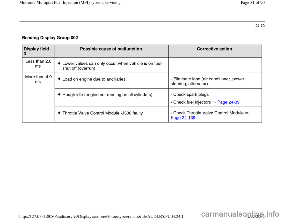
24-70
Reading Display Group 002 Display field
3
Possible cause of malfunction
Corrective action
Less than 2.0
ms
Lower values can only occur when vehicle is on fuel-
shut off (overrun)
More than 4.0
ms Load on engine due to ancillaries- Eliminate load (air conditioner, power
steering, alternator)
Rough idle (engine not running on all cylinders)- Check spark plugs
- Check fuel injectors Page 24
-39
Throttle Valve Control Module -J338 faulty- Check Throttle Valve Control Module
Page 24
-139
Pa
ge 81 of 90 Motronic Multi
port Fuel In
jection
(MFI
) system, servicin
g
11/22/2002 htt
p://127.0.0.1:8080/audi/servlet/Dis
play?action=Goto&t
yp
e=re
pair&id=AUDI.B5.FU04.24.1
Page 82 of 90
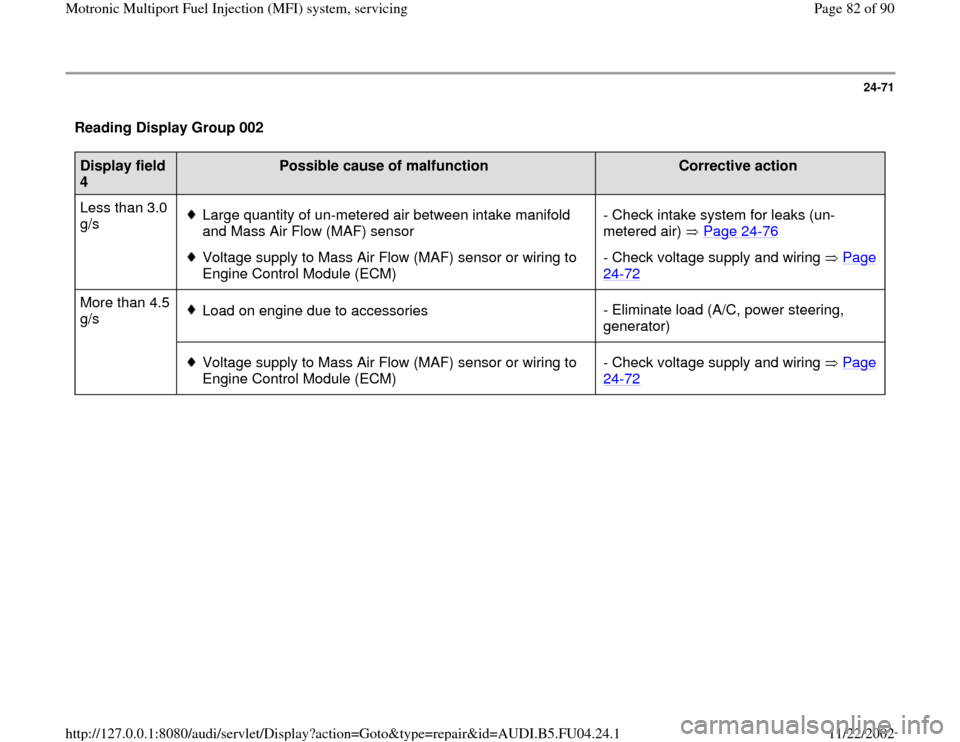
24-71
Reading Display Group 002 Display field
4
Possible cause of malfunction
Corrective action
Less than 3.0
g/s
Large quantity of un-metered air between intake manifold
and Mass Air Flow (MAF) sensor
Voltage supply to Mass Air Flow (MAF) sensor or wiring to
Engine Control Module (ECM) - Check intake system for leaks (un-
metered air) Page 24
-76
- Check voltage supply and wiring Page 24
-72
More than 4.5
g/s
Load on engine due to accessories- Eliminate load (A/C, power steering,
generator)
Voltage supply to Mass Air Flow (MAF) sensor or wiring to
Engine Control Module (ECM) - Check voltage supply and wiring Page
24
-72
Pa
ge 82 of 90 Motronic Multi
port Fuel In
jection
(MFI
) system, servicin
g
11/22/2002 htt
p://127.0.0.1:8080/audi/servlet/Dis
play?action=Goto&t
yp
e=re
pair&id=AUDI.B5.FU04.24.1