engine AUDI A4 1999 B5 / 1.G APB Engine Motronic Multiport Fuel Injection System Servising Workshop Manual
[x] Cancel search | Manufacturer: AUDI, Model Year: 1999, Model line: A4, Model: AUDI A4 1999 B5 / 1.GPages: 90, PDF Size: 0.84 MB
Page 3 of 90
24-2
CAUTION!
To operate the engine at starter speed
without actually starting it (for example, in
order to test compression), unplug the
connectors from the output stages for the
ignition coils and also the connectors on the
injectors.
During some of the tests the control module
may identify and record malfunctions. The
DTC memory should therefore be checked
and (if necessary) erased after completing
the tests and any repair work that may be
required. After erasing DTC memory
generate new readiness code Page 01
-
105
.
Always switch off the ignition before
cleaning the engine.
Always switch off the ignition before
connecting or disconnecting the battery,
otherwise the engine control module may be
damaged.
Be sure of proper radio code (for vehicles
equipped with coded anti-theft radio)
Be sure the battery negative (-) cable is
Pa
ge 3 of 90 Motronic Multi
port Fuel In
jection
(MFI
) system, servicin
g
11/22/2002 htt
p://127.0.0.1:8080/audi/servlet/Dis
play?action=Goto&t
yp
e=re
pair&id=AUDI.B5.FU04.24.1
Page 6 of 90
24-4
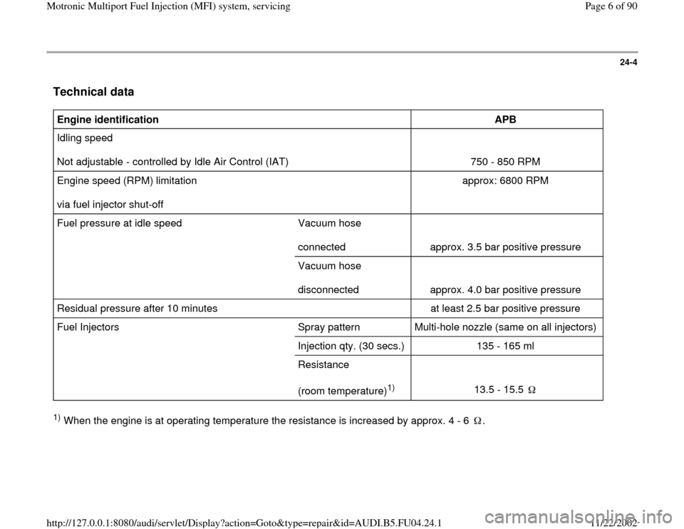
Technical data
Engine identification
APB
Idling speed
Not adjustable - controlled by Idle Air Control (IAT)
750 - 850 RPM
Engine speed (RPM) limitation
via fuel injector shut-off approx: 6800 RPM
Fuel pressure at idle speed Vacuum hose
connected
approx. 3.5 bar positive pressure
Vacuum hose
disconnected
approx. 4.0 bar positive pressure
Residual pressure after 10 minutes at least 2.5 bar positive pressure
Fuel Injectors Spray pattern Multi-hole nozzle (same on all injectors)
Injection qty. (30 secs.) 135 - 165 ml
Resistance
(room temperature)
1)
13.5 - 15.5
1) When the engine is at operating temperature the resistance is increased by approx. 4 - 6 .
Pa
ge 6 of 90 Motronic Multi
port Fuel In
jection
(MFI
) system, servicin
g
11/22/2002 htt
p://127.0.0.1:8080/audi/servlet/Dis
play?action=Goto&t
yp
e=re
pair&id=AUDI.B5.FU04.24.1
Page 9 of 90
24-7
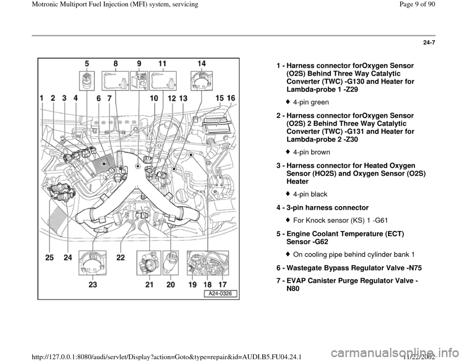
1 -
Harness connector forOxygen Sensor
(O2S) Behind Three Way Catalytic
Converter (TWC) -G130 and Heater for
Lambda-probe 1 -Z29
4-pin green
2 -
Harness connector forOxygen Sensor
(O2S) 2 Behind Three Way Catalytic
Converter (TWC) -G131 and Heater for
Lambda-probe 2 -Z30 4-pin brown
3 -
Harness connector for Heated Oxygen
Sensor (HO2S) and Oxygen Sensor (O2S)
Heater 4-pin black
4 -
3-pin harness connector For Knock sensor (KS) 1 -G61
5 -
Engine Coolant Temperature (ECT)
Sensor -G62 On cooling pipe behind cylinder bank 1
6 -
Wastegate Bypass Regulator Valve -N75
7 -
EVAP Canister Purge Regulator Valve -
N80
Pa
ge 9 of 90 Motronic Multi
port Fuel In
jection
(MFI
) system, servicin
g
11/22/2002 htt
p://127.0.0.1:8080/audi/servlet/Dis
play?action=Goto&t
yp
e=re
pair&id=AUDI.B5.FU04.24.1
Page 10 of 90
24-8
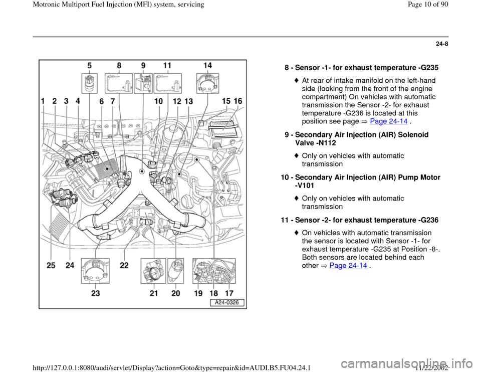
8 -
Sensor -1- for exhaust temperature -G235
At rear of intake manifold on the left-hand
side (looking from the front of the engine
compartment) On vehicles with automatic
transmission the Sensor -2- for exhaust
temperature -G236 is located at this
position see page Page 24
-14
.
9 -
Secondary Air Injection (AIR) Solenoid
Valve -N112
Only on vehicles with automatic
transmission
10 -
Secondary Air Injection (AIR) Pump Motor
-V101 Only on vehicles with automatic
transmission
11 -
Sensor -2- for exhaust temperature -G236 On vehicles with automatic transmission
the sensor is located with Sensor -1- for
exhaust temperature -G235 at Position -8-.
Both sensors are located behind each
other Page 24
-14
.
Pa
ge 10 of 90 Motronic Multi
port Fuel In
jection
(MFI
) system, servicin
g
11/22/2002 htt
p://127.0.0.1:8080/audi/servlet/Dis
play?action=Goto&t
yp
e=re
pair&id=AUDI.B5.FU04.24.1
Page 11 of 90
24-9
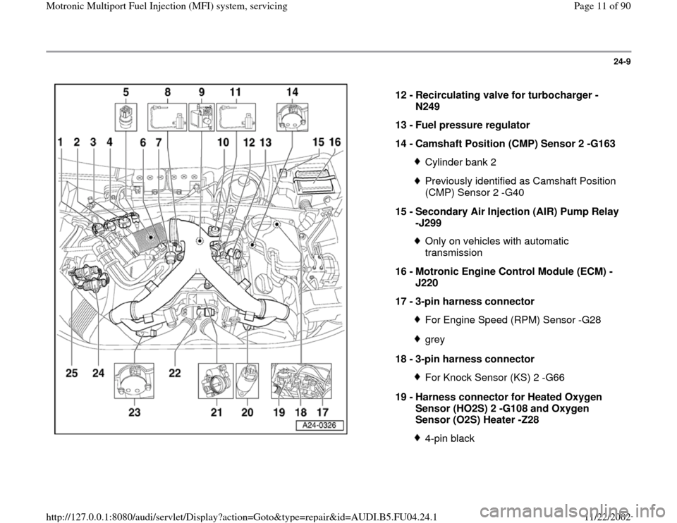
12 -
Recirculating valve for turbocharger -
N249
13 -
Fuel pressure regulator
14 -
Camshaft Position (CMP) Sensor 2 -G163
Cylinder bank 2Previously identified as Camshaft Position
(CMP) Sensor 2 -G40
15 -
Secondary Air Injection (AIR) Pump Relay
-J299 Only on vehicles with automatic
transmission
16 -
Motronic Engine Control Module (ECM) -
J220
17 -
3-pin harness connector For Engine Speed (RPM) Sensor -G28grey
18 -
3-pin harness connector For Knock Sensor (KS) 2 -G66
19 -
Harness connector for Heated Oxygen
Sensor (HO2S) 2 -G108 and Oxygen
Sensor (O2S) Heater -Z28 4-pin black
Pa
ge 11 of 90 Motronic Multi
port Fuel In
jection
(MFI
) system, servicin
g
11/22/2002 htt
p://127.0.0.1:8080/audi/servlet/Dis
play?action=Goto&t
yp
e=re
pair&id=AUDI.B5.FU04.24.1
Page 13 of 90
24-11
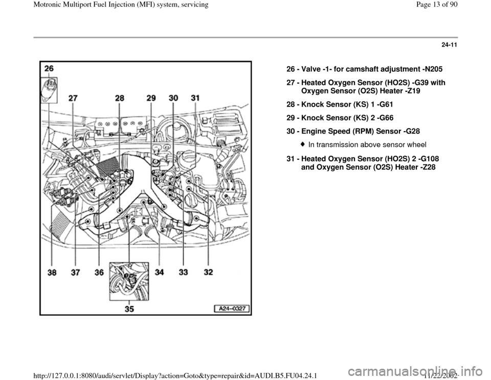
26 -
Valve -1- for camshaft adjustment -N205
27 -
Heated Oxygen Sensor (HO2S) -G39 with
Oxygen Sensor (O2S) Heater -Z19
28 -
Knock Sensor (KS) 1 -G61
29 -
Knock Sensor (KS) 2 -G66
30 -
Engine Speed (RPM) Sensor -G28
In transmission above sensor wheel
31 -
Heated Oxygen Sensor (HO2S) 2 -G108
and Oxygen Sensor (O2S) Heater -Z28
Pa
ge 13 of 90 Motronic Multi
port Fuel In
jection
(MFI
) system, servicin
g
11/22/2002 htt
p://127.0.0.1:8080/audi/servlet/Dis
play?action=Goto&t
yp
e=re
pair&id=AUDI.B5.FU04.24.1
Page 20 of 90
24-18
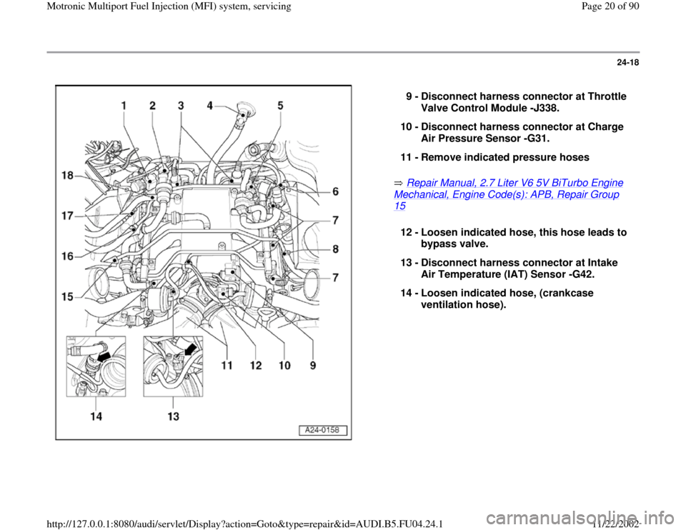
Repair Manual, 2.7 Liter V6 5V BiTurbo Engine
Mechanical, Engine Code(s): APB, Repair Group 15
9 -
Disconnect harness connector at Throttle
Valve Control Module -J338.
10 -
Disconnect harness connector at Charge
Air Pressure Sensor -G31.
11 -
Remove indicated pressure hoses 12 -
Loosen indicated hose, this hose leads to
bypass valve.
13 -
Disconnect harness connector at Intake
Air Temperature (IAT) Sensor -G42.
14 -
Loosen indicated hose, (crankcase
ventilation hose).
Pa
ge 20 of 90 Motronic Multi
port Fuel In
jection
(MFI
) system, servicin
g
11/22/2002 htt
p://127.0.0.1:8080/audi/servlet/Dis
play?action=Goto&t
yp
e=re
pair&id=AUDI.B5.FU04.24.1
Page 22 of 90
24-20
Wiring and component check with
VAG1598/31 test box
Notes:
The VAG1598/31 test box is designed so it can
be simultaneously connected to the control
module wiring harness and to the control
module itself.
This has the advantage of enabling the engine
management system to remain fully operational
even with the test box connected (for example,
when testing signals while the engine is
running).
The instructions for performing the individual
tests indicate whether or not the engine control
module itself also needs to be connected to the
test box.
Use the hand multimeter Fluke 83 (or
equivalent) or the multimeter VAG1715 and the
diode test lamp VAG1527 for the checks.
To connect the testers to VAG1598/31 test box,
always use the adapter leads from VAG1594 A
connector test kit.
Required special tools and test equipment
Pa
ge 22 of 90 Motronic Multi
port Fuel In
jection
(MFI
) system, servicin
g
11/22/2002 htt
p://127.0.0.1:8080/audi/servlet/Dis
play?action=Goto&t
yp
e=re
pair&id=AUDI.B5.FU04.24.1
Page 24 of 90
24-21
Work sequence
- Switch off ignition.
- Pull rubber gasket forward.
- Remove plenum cover forward.
- Remove cover for E-box (in plenum chamber).
CAUTION!
To prevent damage to the electronic components, switch to the
respective measuring range before connecting the measuring cable
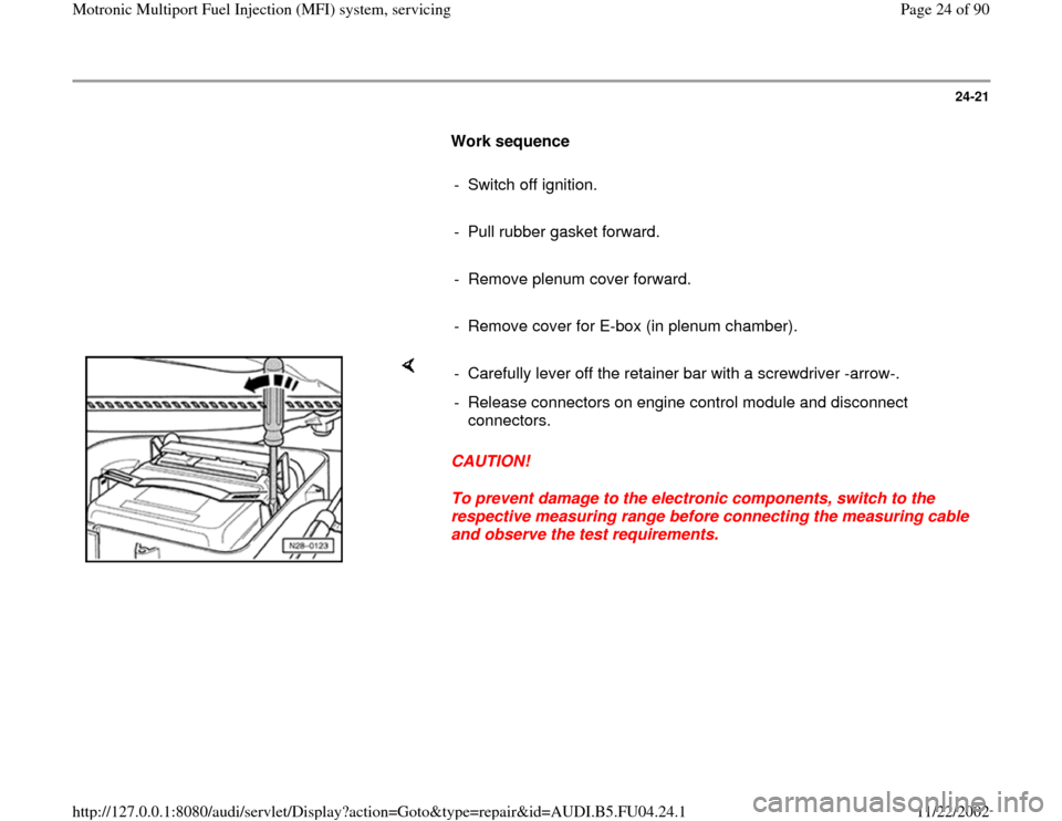
and observe the test requirements. - Carefully lever off the retainer bar with a screwdriver -arrow-.
- Release connectors on engine control module and disconnect
connectors.
Pa
ge 24 of 90 Motronic Multi
port Fuel In
jection
(MFI
) system, servicin
g
11/22/2002 htt
p://127.0.0.1:8080/audi/servlet/Dis
play?action=Goto&t
yp
e=re
pair&id=AUDI.B5.FU04.24.1
Page 25 of 90
24-22
After installing the engine control module, carry out the following
operation
Note:
At the first learning (adaptation) phase during the "Engine-Basic Setting"
the engine might run a little rough at idle and bucks/jerks a little while
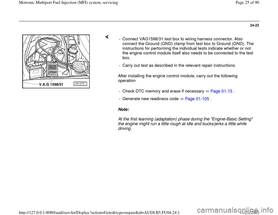
driving. - Connect VAG1598/31 test box to wiring harness connector. Also
connect the Ground (GND) clamp from test box to Ground (GND). The
instructions for performing the individual tests indicate whether or not
the engine control module itself also needs to be connected to the test
box.
- Carry out test as described in the relevant repair instructions.
- Check DTC memory and erase if necessary Page 01
-15
.
- Generate new readiness code Page 01
-105
.
Pa
ge 25 of 90 Motronic Multi
port Fuel In
jection
(MFI
) system, servicin
g
11/22/2002 htt
p://127.0.0.1:8080/audi/servlet/Dis
play?action=Goto&t
yp
e=re
pair&id=AUDI.B5.FU04.24.1