air condition AUDI A4 1999 B5 / 1.G APB Engine Motronic Syst
[x] Cancel search | Manufacturer: AUDI, Model Year: 1999, Model line: A4, Model: AUDI A4 1999 B5 / 1.GPages: 166, PDF Size: 0.53 MB
Page 9 of 166
01-7
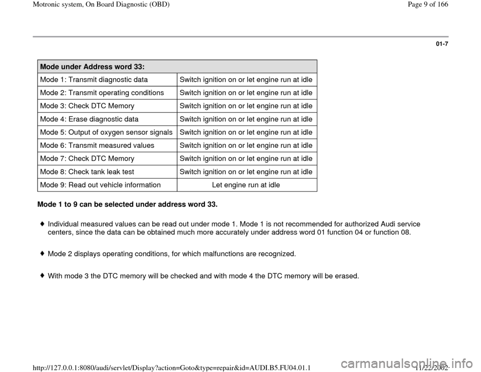
Mode under Address word 33:
Mode 1: Transmit diagnostic data Switch ignition on or let engine run at idle
Mode 2: Transmit operating conditions Switch ignition on or let engine run at idle
Mode 3: Check DTC Memory Switch ignition on or let engine run at idle
Mode 4: Erase diagnostic data Switch ignition on or let engine run at idle
Mode 5: Output of oxygen sensor signals Switch ignition on or let engine run at idle
Mode 6: Transmit measured values Switch ignition on or let engine run at idle
Mode 7: Check DTC Memory Switch ignition on or let engine run at idle
Mode 8: Check tank leak test Switch ignition on or let engine run at idle
Mode 9: Read out vehicle information Let engine run at idle Mode 1 to 9 can be selected under address word 33.
Individual measured values can be read out under mode 1. Mode 1 is not recommended for authorized Audi service
centers, since the data can be obtained much more accurately under address word 01 function 04 or function 08.
Mode 2 displays operating conditions, for which malfunctions are recognized.
With mode 3 the DTC memory will be checked and with mode 4 the DTC memory will be erased.
Pa
ge 9 of 166 Motronic s
ystem, On Board Dia
gnostic
(OBD
)
11/22/2002 htt
p://127.0.0.1:8080/audi/servlet/Dis
play?action=Goto&t
yp
e=re
pair&id=AUDI.B5.FU04.01.1
Page 20 of 166
01-17
-
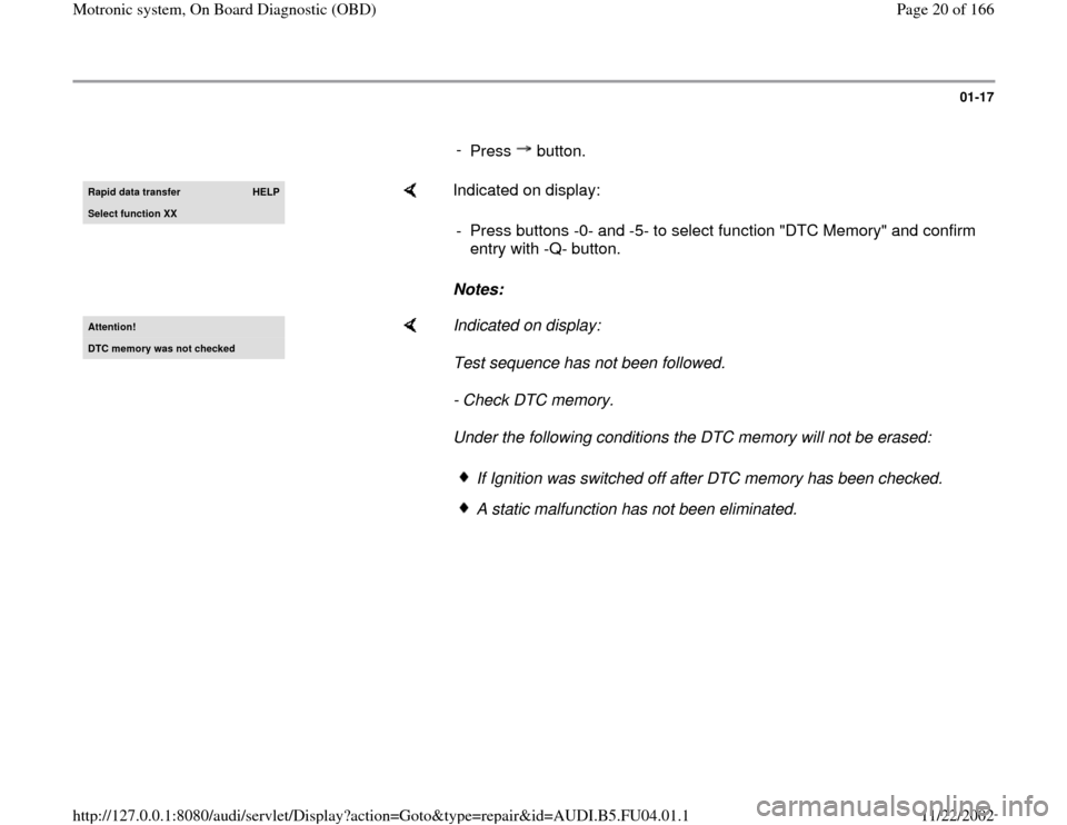
Press button.Rapid data transfer
HELP
Select function XX
Indicated on display:
Notes: - Press buttons -0- and -5- to select function "DTC Memory" and confirm
entry with -Q- button.
Attention!DTC memor
y was not checked
Indicated on display:
Test sequence has not been followed.
- Check DTC memory.
Under the following conditions the DTC memory will not be erased:
If Ignition was switched off after DTC memory has been checked.A static malfunction has not been eliminated.
Pa
ge 20 of 166 Motronic s
ystem, On Board Dia
gnostic
(OBD
)
11/22/2002 htt
p://127.0.0.1:8080/audi/servlet/Dis
play?action=Goto&t
yp
e=re
pair&id=AUDI.B5.FU04.01.1
Page 109 of 166
01-90
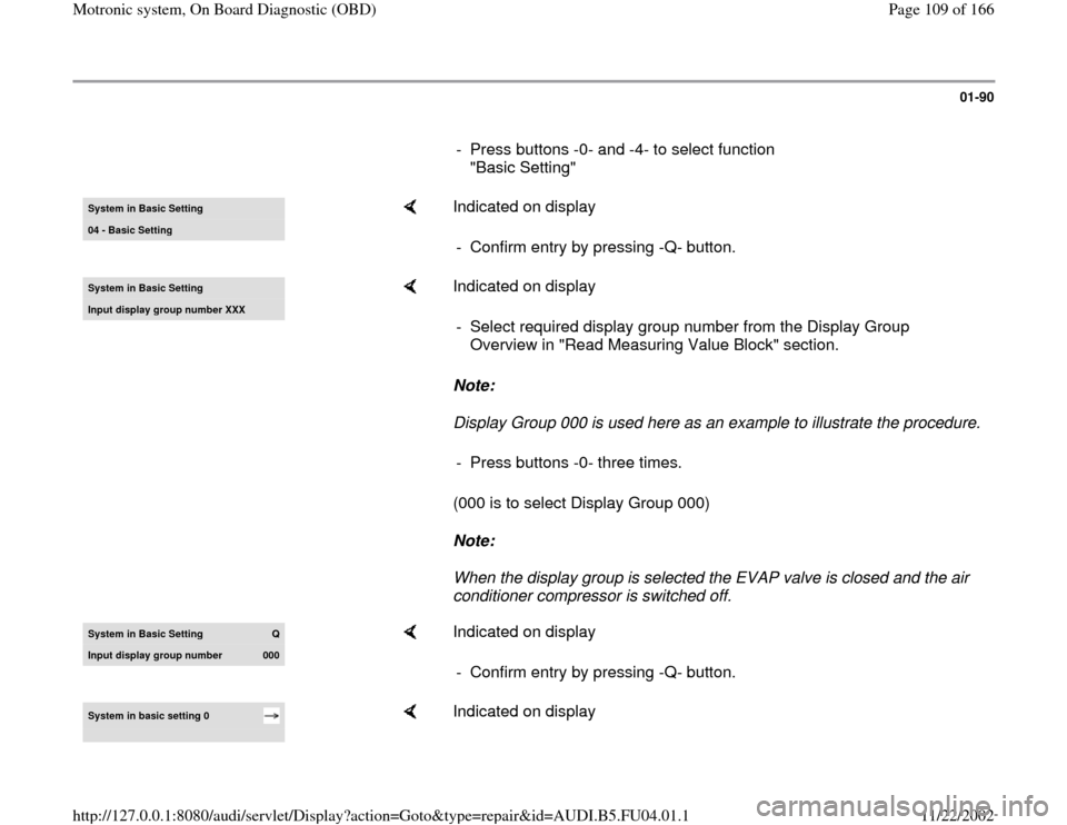
- Press buttons -0- and -4- to select function
"Basic Setting" System in Basic Settin
g
04 - Basic Settin
g
Indicated on display
- Confirm entry by pressing -Q- button.
System in Basic Setting Input displa
y group number XXX
Indicated on display
Note:
Display Group 000 is used here as an example to illustrate the procedure.
(000 is to select Display Group 000)
Note:
When the display group is selected the EVAP valve is closed and the air
conditioner compressor is switched off. - Select required display group number from the Display Group
Overview in "Read Measuring Value Block" section.
- Press buttons -0- three times.
System in Basic Settin
g
Q
Input display group number
000
Indicated on display
- Confirm entry by pressing -Q- button.
System in basic setting 0
Indicated on display
Pa
ge 109 of 166 Motronic s
ystem, On Board Dia
gnostic
(OBD
)
11/22/2002 htt
p://127.0.0.1:8080/audi/servlet/Dis
play?action=Goto&t
yp
e=re
pair&id=AUDI.B5.FU04.01.1
Page 121 of 166

01-100
The readiness code will be reset to "1 1 1 1 1
1 1 1" if:
The DTC memory was erased
A new Engine Control Module was installed
If the voltage supply has been disconnected
from the Engine Control Module (ECM)
In this case the readiness code must be
generated Page 01
-105
.
During driving operation in various load
conditions, exhaust relevant tests are performed
by the control module within a "short trip" and
readiness code is generated on its own. In this
case, however, concluding control possibilities
are not available, meaning that it will not be
indicated whether all positions of the readiness
code are set to "0."
Pa
ge 121 of 166 Motronic s
ystem, On Board Dia
gnostic
(OBD
)
11/22/2002 htt
p://127.0.0.1:8080/audi/servlet/Dis
play?action=Goto&t
yp
e=re
pair&id=AUDI.B5.FU04.01.1
Page 131 of 166

01-109
Display fields
1 2 3 4
Display group 060: Adaptation of throttle valve control module
Display xx % xx %
x
---
Indicated Throttle
valve angle
(angle
sensor 1) Throttle
valve angle
(angle
sensor 2) Adaptation step counter
Adaptation condition
Work area 0 - 100 % 0 - 100 %
0 - 8
ADP. runs
ADP. OK
ADP. ERROR
Specified
value 3 - 93 % 97 - 3 %
8
ADP. OK
Note:
During adaptation, adaptation step counter
must reach the number 8. (Some numbers
may be skipped). If "ADP. ERROR." is displayed:
Check DTC memory Page
01
-15
.
If specified value is not
obtained: Note, Page Page
24
-152
.
Note for display field 3:
During adaptation different digits are displayed in display field 3, which indicate the particular adaptation condition. It is not
important what the adaptation step counter (display field 3) displays during adaptation, rather that display field 4 displays the
Pa
ge 131 of 166 Motronic s
ystem, On Board Dia
gnostic
(OBD
)
11/22/2002 htt
p://127.0.0.1:8080/audi/servlet/Dis
play?action=Goto&t
yp
e=re
pair&id=AUDI.B5.FU04.01.1
Page 135 of 166

01-111
Display fields
1 2 3 4
Display group 070: Diagnostic of EVAP canister purge regulator valve
Display xx % xx.x % xx %
Test ON
Indicated EVAP valve duty
cycle during
diagnosis Oxygen sensor
control deviation
during diagnosis Relative
Ground via
EVAP valve Diagnostic condition
Work
Range min.: 0 %
max.: 100 % min.: -25.0 %
max.: 25.0 %
Test OFF
Test ON
EVAP OK
EVAP n.OK
Abort
Specified
value xx % -5.0 to 4.0 %
xx - xx %
1)
EVAP OK
Note:
If "EVAP n. OK" is displayed: Check DTC
memory Page 01
-15
. Check EVAP canister
purge regulator valve -N80 Page 24
-134
1) A display appears only, if the diagnostic result occurred via deviation from the Idle Air Control (IAC) in a specified tolerance
range and not from deviation from the oxygen sensor control (e.g.: oxygen sensor 1 from EVAP canister). Display field 3 is
only indicated if there is a deviation.
Pa
ge 135 of 166 Motronic s
ystem, On Board Dia
gnostic
(OBD
)
11/22/2002 htt
p://127.0.0.1:8080/audi/servlet/Dis
play?action=Goto&t
yp
e=re
pair&id=AUDI.B5.FU04.01.1
Page 137 of 166
01-113
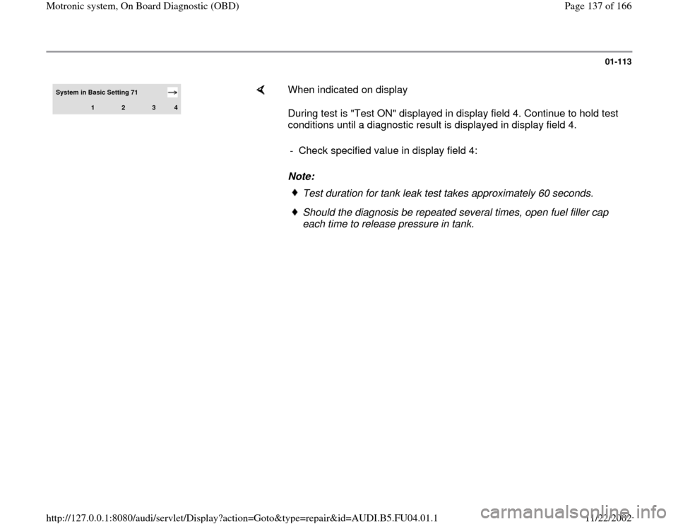
System in Basic Setting 71
1
2
3
4
When indicated on display
During test is "Test ON" displayed in display field 4. Continue to hold test
conditions until a diagnostic result is displayed in display field 4.
Note: - Check specified value in display field 4:
Test duration for tank leak test takes approximately 60 seconds.Should the diagnosis be repeated several times, open fuel filler cap
each time to release pressure in tank.
Pa
ge 137 of 166 Motronic s
ystem, On Board Dia
gnostic
(OBD
)
11/22/2002 htt
p://127.0.0.1:8080/audi/servlet/Dis
play?action=Goto&t
yp
e=re
pair&id=AUDI.B5.FU04.01.1
Page 138 of 166

01-114
Display fields
1 2 3 4
Display group 071: Diagnostic of tank leak test
Display Reed open --- System Test
Test ON
Indicated Condition Reed-
contact malfunction
message System
condition Diagnostic condition and Diagnostic result
Work range Reed open
Reed closed Small leak
Large leak
System not OK System Test
Measurement
Measurement
END Test OFF
Test ON
Syst. OK
Syst. not OK
Abort
Specified
value Reed open --- Measurement
END Syst. OK
Note
If "System not OK" is displayed: Check DTC
memory Page 01
-15
.
Pa
ge 138 of 166 Motronic s
ystem, On Board Dia
gnostic
(OBD
)
11/22/2002 htt
p://127.0.0.1:8080/audi/servlet/Dis
play?action=Goto&t
yp
e=re
pair&id=AUDI.B5.FU04.01.1
Page 140 of 166

01-116
Display fields
1 2 3 4
Display group 107: Diagnostic of fuel supply
Display xxx /RPM x.x % x.x %
Test ON
Indicated Engine speed
(actual) Oxygen sensor control
average value (Bank 1) Oxygen sensor control
average value (Bank 2) Diagnostic condition
Work
range min.: 750 /RPM
max.:
6800 /RPM min.: -25.0 %
max.: 25.0 % min.: -25.0 %
max.: 25.0 % Test OFF
Test ON
Syst. OK
Syst. n OK
Value 750 - 850/RPM -18.0 % to 12.0 % -18.0 % to 12.0 % Syst. OK
Note
If "Syst. n OK" appears, check
DTC memory Page 01
-15
.
Pa
ge 140 of 166 Motronic s
ystem, On Board Dia
gnostic
(OBD
)
11/22/2002 htt
p://127.0.0.1:8080/audi/servlet/Dis
play?action=Goto&t
yp
e=re
pair&id=AUDI.B5.FU04.01.1
Page 142 of 166
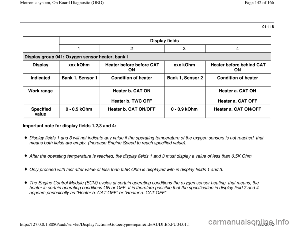
01-118
Display fields
1 2 3 4
Display group 041: Oxygen sensor heater, bank 1
Display
xxx kOhm
Heater before before CAT
ON xxx kOhm
Heater before behind CAT
ON
Indicated
Bank 1, Sensor 1
Condition of heater
Bank 1, Sensor 2
Condition of heater
Work range
Heater b. CAT ON
Heater b. TWC OFF
Heater a. CAT ON
Heater a. CAT OFF
Specified
value 0 - 0.5 kOhm
Heater b. CAT ON/OFF
0 - 0.9 kOhm
Heater a. CAT ON/OFF Important note for display fields 1,2,3 and 4:
Display fields 1 and 3 will not indicate any value if the operating temperature of the oxygen sensors is not reached, that
means both fields are empty. (Increase Engine Speed to reach specified value).
After the operating temperature is reached, the display fields 1 and 3 must display a value of less than 0.5K Ohm
Only proceed with test after value of less than 0.5K Ohm is displayed with in display fields 1 and 3.
The Engine Control Module (ECM) cycles at certain operating conditions the oxygen sensor heating, that means, the
heater is certain operating conditions ON or OFF. It is therefore possible that the specification in display field 2 and 4
appears periodically as "Heater b. CAT OFF" or "Heater a. CAT OFF"
Pa
ge 142 of 166 Motronic s
ystem, On Board Dia
gnostic
(OBD
)
11/22/2002 htt
p://127.0.0.1:8080/audi/servlet/Dis
play?action=Goto&t
yp
e=re
pair&id=AUDI.B5.FU04.01.1