transmission AUDI A4 1999 B5 / 1.G APB Engine Motronic Syst
[x] Cancel search | Manufacturer: AUDI, Model Year: 1999, Model line: A4, Model: AUDI A4 1999 B5 / 1.GPages: 166, PDF Size: 0.53 MB
Page 3 of 166
01-3
Exhaust Malfunction Indicator Light
(MIL), significance
If the Engine Control Module (ECM) recognizes
emission related malfunctions, this is indicates by
the MIL coming on.
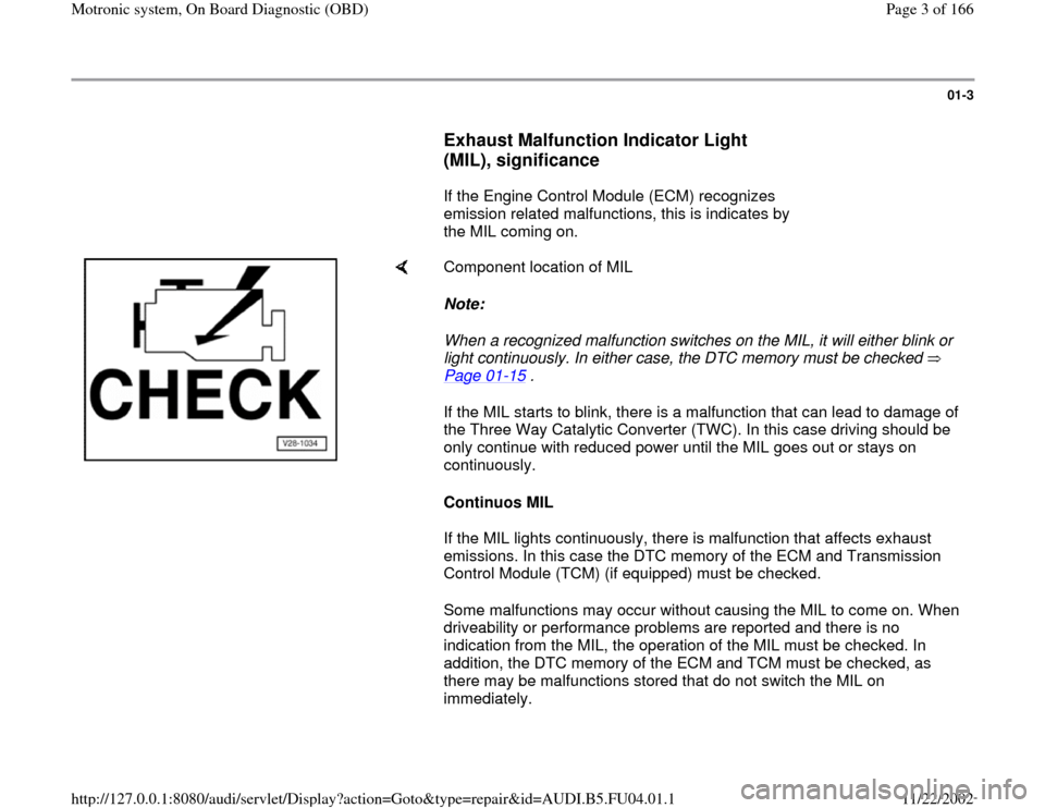
Component location of MIL
Note:
When a recognized malfunction switches on the MIL, it will either blink or
light continuously. In either case, the DTC memory must be checked
Page 01
-15
.
If the MIL starts to blink, there is a malfunction that can lead to damage of
the Three Way Catalytic Converter (TWC). In this case driving should be
only continue with reduced power until the MIL goes out or stays on
continuously.
Continuos MIL
If the MIL lights continuously, there is malfunction that affects exhaust
emissions. In this case the DTC memory of the ECM and Transmission
Control Module (TCM) (if equipped) must be checked.
Some malfunctions may occur without causing the MIL to come on. When
driveability or performance problems are reported and there is no
indication from the MIL, the operation of the MIL must be checked. In
addition, the DTC memory of the ECM and TCM must be checked, as
there may be malfunctions stored that do not switch the MIL on
immediately.
Pa
ge 3 of 166 Motronic s
ystem, On Board Dia
gnostic
(OBD
)
11/22/2002 htt
p://127.0.0.1:8080/audi/servlet/Dis
play?action=Goto&t
yp
e=re
pair&id=AUDI.B5.FU04.01.1
Page 11 of 166
01-9
Vehicle diagnostic, testing and
information system VAS5051 or
VAG1551, connecting and selecting
functions
Requirements
Fuses for engine electronics OK
Fuel pump relay OK
Battery voltage at least 11 V
Ground (GND) connection for engine and
transmission OK
- Switch ignition off.
Note:
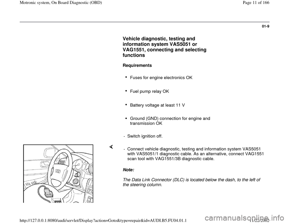
The Data Link Connector (DLC) is located below the dash, to the left of
the steering column. - Connect vehicle diagnostic, testing and information system VAS5051
with VAS5051/1 diagnostic cable. As an alternative, connect VAG1551
scan tool with VAG1551/3B diagnostic cable.
Pa
ge 11 of 166 Motronic s
ystem, On Board Dia
gnostic
(OBD
)
11/22/2002 htt
p://127.0.0.1:8080/audi/servlet/Dis
play?action=Goto&t
yp
e=re
pair&id=AUDI.B5.FU04.01.1
Page 84 of 166
01-70
DTC
Description of malfunction
Corrective action
SAE
VAG
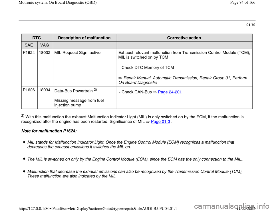
P1624 18032 MIL Request Sign. active Exhaust relevant malfunction from Transmission Control Module (TCM),
MIL is switched on by TCM
Repair Manual, Automatic Transmission, Repair Group 01, Perform
On Board Diagnostic - Check DTC Memory of TCM
P1626 18034
Data-Bus Powertrain
2)
Missing message from fuel
injection pump - Check CAN-Bus Page 24
-201
2) With this malfunction the exhaust Malfunction Indicator Light (MIL) is only switched on by the ECM, if the malfunction is
recognized after the engine has been restarted. Significance of MIL Page 01
-3 .
Note for malfunction P1624:
MIL stands for Malfunction Indicator Light. Once the Engine Control Module (ECM) recognizes a malfunction that
decreases the exhaust emissions it switches the MIL on.
The MIL is switched on only by the Engine Control Module (ECM), since the ECM has the only connection to the MIL..
Malfunction that decrease the exhaust emissions can also be recognized by the Transmission Control Module (TCM),
These malfunction are also indicated by the MIL.
Pa
ge 84 of 166 Motronic s
ystem, On Board Dia
gnostic
(OBD
)
11/22/2002 htt
p://127.0.0.1:8080/audi/servlet/Dis
play?action=Goto&t
yp
e=re
pair&id=AUDI.B5.FU04.01.1
Page 85 of 166
Once the TCM recognizes a malfunction that decreases the exhaust emissions it sends a message to the ECM, the ECM
then switches the MIL on. Parallel to this is the malfunction P1624 stored in the ECM noting that the MIL is switched on
due to a transmission problem and not because of a engine problem.
Pa
ge 85 of 166 Motronic s
ystem, On Board Dia
gnostic
(OBD
)
11/22/2002 htt
p://127.0.0.1:8080/audi/servlet/Dis
play?action=Goto&t
yp
e=re
pair&id=AUDI.B5.FU04.01.1
Page 87 of 166
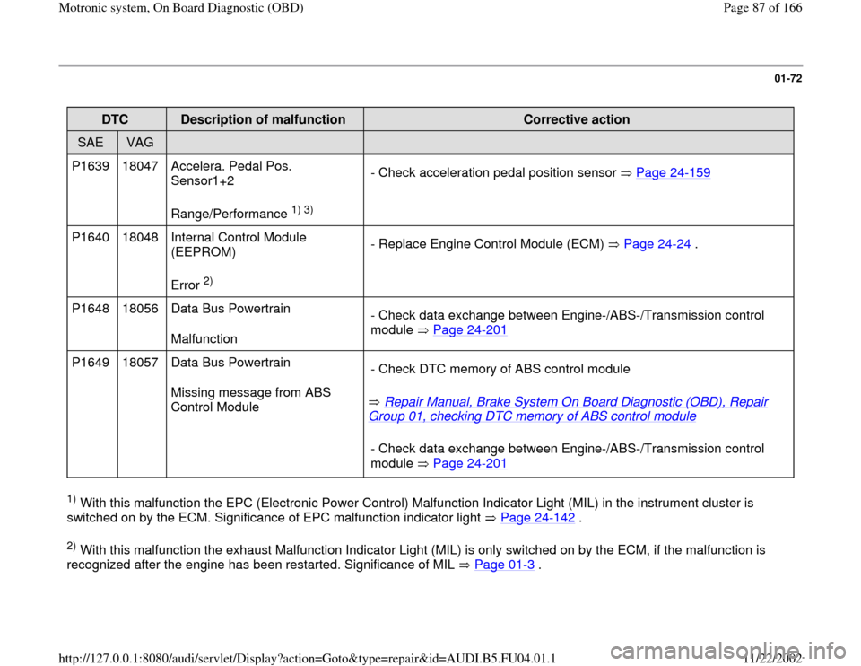
01-72
DTC
Description of malfunction
Corrective action
SAE
VAG
P1639 18047 Accelera. Pedal Pos.
Sensor1+2
Range/Performance
1) 3)
- Check acceleration pedal position sensor Page 24
-159
P1640 18048 Internal Control Module
(EEPROM)
Error
2) - Replace Engine Control Module (ECM) Page 24
-24
.
P1648 18056 Data Bus Powertrain
Malfunction - Check data exchange between Engine-/ABS-/Transmission control
module Page 24
-201
P1649 18057 Data Bus Powertrain
Missing message from ABS
Control Module Repair Manual, Brake System On Board Diagnostic (OBD), Repair
Group 01, checking DTC memory of ABS control module
- Check DTC memory of ABS control module
- Check data exchange between Engine-/ABS-/Transmission control
module Page 24
-201
1) With this malfunction the EPC (Electronic Power Control) Malfunction Indicator Light (MIL) in the instrument cluster is
switched on by the ECM. Significance of EPC malfunction indicator light Page 24
-142
.
2) With this malfunction the exhaust Malfunction Indicator Light (MIL) is only switched on by the ECM, if the malfunction is
recognized after the engine has been restarted. Significance of MIL Page 01
-3 .
Pa
ge 87 of 166 Motronic s
ystem, On Board Dia
gnostic
(OBD
)
11/22/2002 htt
p://127.0.0.1:8080/audi/servlet/Dis
play?action=Goto&t
yp
e=re
pair&id=AUDI.B5.FU04.01.1
Page 91 of 166
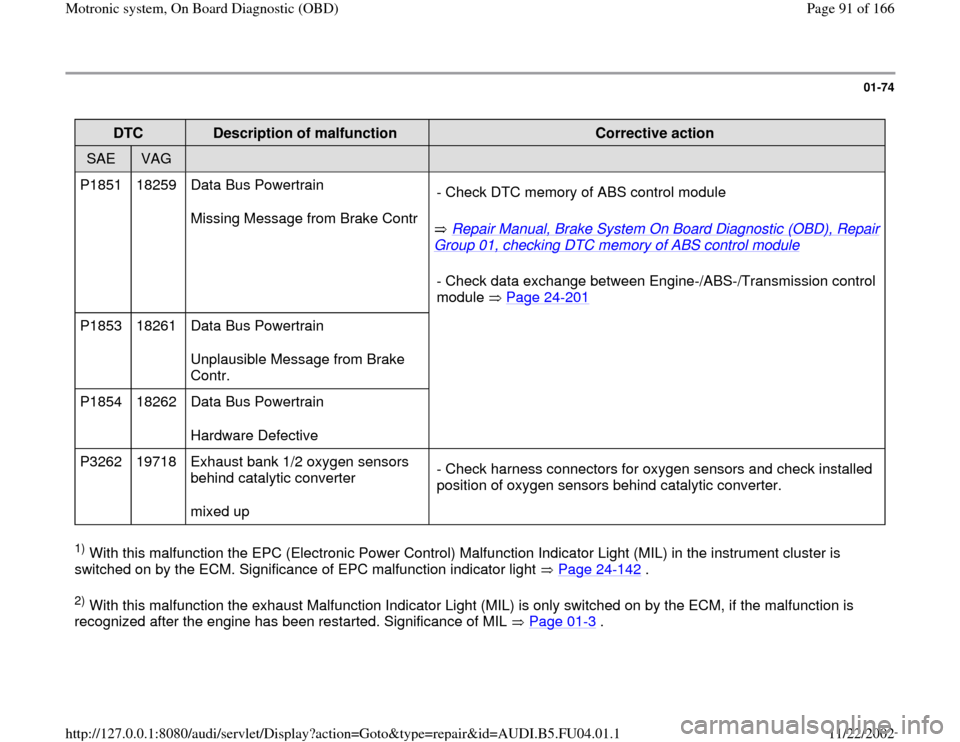
01-74
DTC
Description of malfunction
Corrective action
SAE
VAG
P1851 18259 Data Bus Powertrain
Missing Message from Brake Contr
Repair Manual, Brake System On Board Diagnostic (OBD), Repair
Group 01, checking DTC memory of ABS control module
- Check DTC memory of ABS control module
- Check data exchange between Engine-/ABS-
/Transmission control
module Page 24
-201
P1853 18261 Data Bus Powertrain
Unplausible Message from Brake
Contr.
P1854 18262 Data Bus Powertrain
Hardware Defective
P3262 19718 Exhaust bank 1/2 oxygen sensors
behind catalytic converter
mixed up - Check harness connectors for oxygen sensors and check installed
position of oxygen sensors behind catalytic converter. 1) With this malfunction the EPC (Electronic Power Control) Malfunction Indicator Light (MIL) in the instrument cluster is
switched on by the ECM. Significance of EPC malfunction indicator light Page 24
-142
.
2) With this malfunction the exhaust Malfunction Indicator Light (MIL) is only switched on by the ECM, if the malfunction is
recognized after the engine has been restarted. Significance of MIL Page 01
-3 .
Pa
ge 91 of 166 Motronic s
ystem, On Board Dia
gnostic
(OBD
)
11/22/2002 htt
p://127.0.0.1:8080/audi/servlet/Dis
play?action=Goto&t
yp
e=re
pair&id=AUDI.B5.FU04.01.1
Page 93 of 166
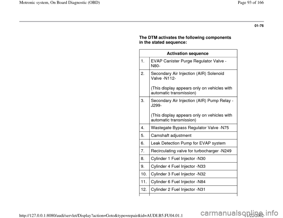
01-76
The DTM activates the following components
in the stated sequence:
Activation sequence
1. EVAP Canister Purge Regulator Valve -
N80-
2. Secondary Air Injection (AIR) Solenoid
Valve -N112-
(This display appears only on vehicles with
automatic transmission)
3. Secondary Air Injection (AIR) Pump Relay -
J299-
(This display appears only on vehicles with
automatic transmission)
4. Wastegate Bypass Regulator Valve -N75
5. Camshaft adjustment
6. Leak Detection Pump for EVAP system
7. Recirculating valve for turbocharger -N249
8. Cylinder 1 Fuel Injector -N30
9. Cylinder 4 Fuel Injector -N33
10. Cylinder 3 Fuel Injector -N32
11. Cylinder 6 Fuel Injector -N84
12. Cylinder 2 Fuel Injector -N31
Pa
ge 93 of 166 Motronic s
ystem, On Board Dia
gnostic
(OBD
)
11/22/2002 htt
p://127.0.0.1:8080/audi/servlet/Dis
play?action=Goto&t
yp
e=re
pair&id=AUDI.B5.FU04.01.1
Page 97 of 166
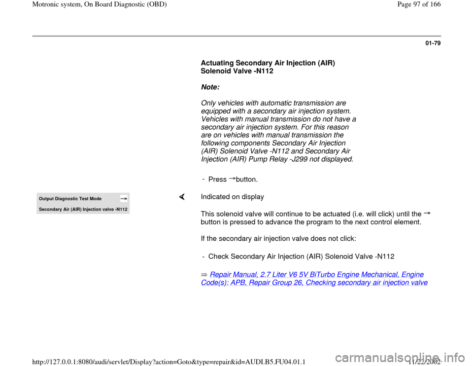
01-79
Actuating Secondary Air Injection (AIR)
Solenoid Valve -N112
Note:
Only vehicles with automatic transmission are
equipped with a secondary air injection system.
Vehicles with manual transmission do not have a
secondary air injection system. For this reason
are on vehicles with manual transmission the
following components Secondary Air Injection
(AIR) Solenoid Valve -N112 and Secondary Air
Injection (AIR) Pump Relay -J299 not displayed.
-
Press button.Output Diagnostic Test Mode Secondar
y Air
(AIR
) Injection valve -N112
Indicated on display
This solenoid valve will continue to be actuated (i.e. will click) until the
button is pressed to advance the program to the next control element.
If the secondary air injection valve does not click:
Repair Manual, 2.7 Liter V6 5V BiTurbo Engine Mechanical, Engine Code(s): APB, Repair Group 26, Checking secondary air injection valve
- Check Secondary Air Injection (AIR) Solenoid Valve -N112
Pa
ge 97 of 166 Motronic s
ystem, On Board Dia
gnostic
(OBD
)
11/22/2002 htt
p://127.0.0.1:8080/audi/servlet/Dis
play?action=Goto&t
yp
e=re
pair&id=AUDI.B5.FU04.01.1
Page 98 of 166
01-80
Actuating Secondary Air Injection (AIR) Pump
Relay -J299
Note:
Only vehicles with automatic transmission are
equipped with a secondary air injection system.
Vehicles with manual transmission do not have a
secondary air injection system. For this reason is
on vehicles with manual transmission the
following component Secondary Air Injection
(AIR) Pump Relay -J299 not displayed.
-
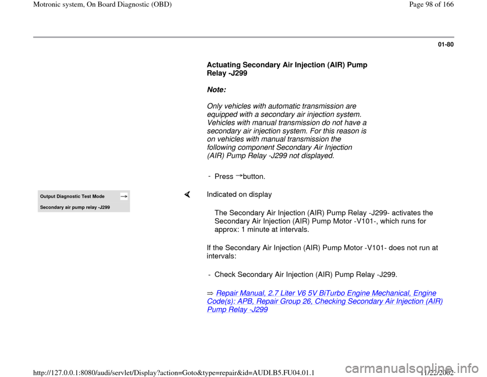
Press button.Output Diagnostic Test Mode Secondar
y air pump rela
y -J299
Indicated on display
If the Secondary Air Injection (AIR) Pump Motor -V101- does not run at
intervals:
Repair Manual, 2.7 Liter V6 5V BiTurbo Engine Mechanical, Engine Code(s): APB, Repair Group 26, Checking Secondary Air Injection (AIR) Pump Relay
-J299
The Secondary Air Injection (AIR) Pump Relay -J299- activates the
Secondary Air Injection (AIR) Pump Motor -V101-, which runs for
approx: 1 minute at intervals.
- Check Secondary Air Injection (AIR) Pump Relay -J299.
Pa
ge 98 of 166 Motronic s
ystem, On Board Dia
gnostic
(OBD
)
11/22/2002 htt
p://127.0.0.1:8080/audi/servlet/Dis
play?action=Goto&t
yp
e=re
pair&id=AUDI.B5.FU04.01.1
Page 106 of 166
01-88
Basic setting
With the ignition on and engine not running,
the following operation can be performed in
the "Basic setting" mode (function 04):
Adaptation of throttle valve control module to
ECM Page 24
-146
Vehicles with automatic transmission:
Adaptation of kick down function of accelerator
pedal position sensor to ECM Display group
63 ( Page 24
-166
)
With the engine running, the following
operations can be performed in the basic
setting mode "Function 04":
Learning process (adaptation) for oxygen
sensor control every display group
Troubleshooting by targeted activation and
deactivation of oxygen sensor control display
group 99 (Observe note on page Page 24
-
81
).
Pa
ge 106 of 166 Motronic s
ystem, On Board Dia
gnostic
(OBD
)
11/22/2002 htt
p://127.0.0.1:8080/audi/servlet/Dis
play?action=Goto&t
yp
e=re
pair&id=AUDI.B5.FU04.01.1