tow AUDI A4 1999 B5 / 1.G APB Engine Valve Gear Service Workshop Manual
[x] Cancel search | Manufacturer: AUDI, Model Year: 1999, Model line: A4, Model: AUDI A4 1999 B5 / 1.GPages: 99, PDF Size: 1.78 MB
Page 37 of 99
15-37
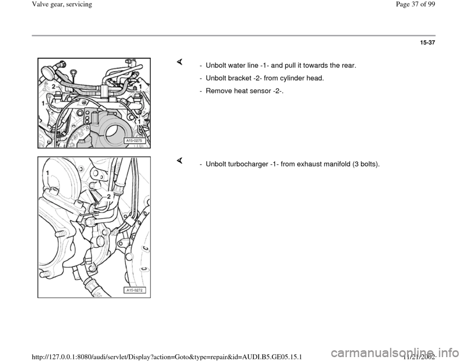
- Unbolt water line -1- and pull it towards the rear.
- Unbolt bracket -2- from cylinder head.
- Remove heat sensor -2-.
- Unbolt turbocharger -1- from exhaust manifold (3 bolts).
Pa
ge 37 of 99 Valve
gear, servicin
g
11/21/2002 htt
p://127.0.0.1:8080/audi/servlet/Dis
play?action=Goto&t
yp
e=re
pair&id=AUDI.B5.GE05.15.1
Page 40 of 99
15-40
- Before installing cylinder head in position, turn
crankshaft and camshafts to TDC of No. 3
cylinder.
- Install cylinder head gasket on dowel sleeves.
The marking "oben" (top) or part number must
face towards cylinder head.
- Install cylinder head, insert cylinder head bolts
and tighten finger-tight.
It is not necessary to torque down cylinder head bolts again after repairs
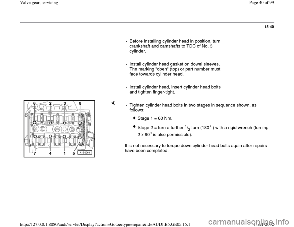
have been completed. - Tighten cylinder head bolts in two stages in sequence shown, as
follows:
Stage 1 = 60 Nm.
Stage 2 = turn a further
1/2 turn (180 ) with a rigid wrench (turning
2 x 90 is also permissible).
Pa
ge 40 of 99 Valve
gear, servicin
g
11/21/2002 htt
p://127.0.0.1:8080/audi/servlet/Dis
play?action=Goto&t
yp
e=re
pair&id=AUDI.B5.GE05.15.1
Page 50 of 99
15-50
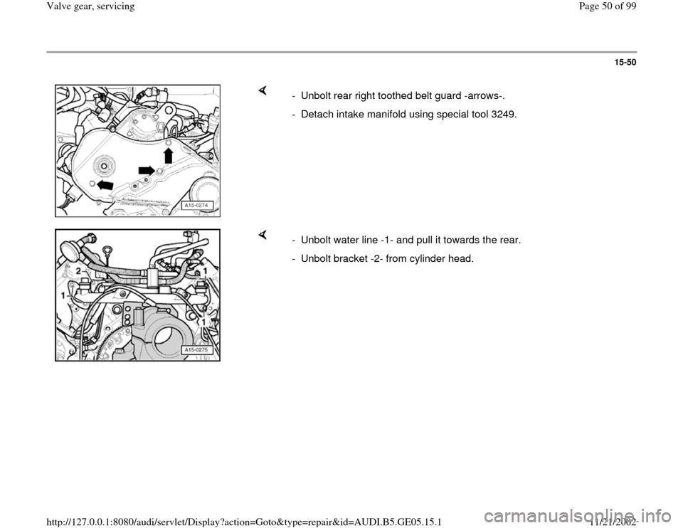
- Unbolt rear right toothed belt guard -arrows-.
- Detach intake manifold using special tool 3249.
- Unbolt water line -1- and pull it towards the rear.
- Unbolt bracket -2- from cylinder head.
Pa
ge 50 of 99 Valve
gear, servicin
g
11/21/2002 htt
p://127.0.0.1:8080/audi/servlet/Dis
play?action=Goto&t
yp
e=re
pair&id=AUDI.B5.GE05.15.1
Page 54 of 99
15-54
- Before installing cylinder head in position, turn
crankshaft and camshafts to TDC of No. 3
cylinder.
- Install cylinder head gasket on dowel sleeves.
Marking "oben" (top) or part number must face
towards cylinder head.
- Install cylinder head, insert cylinder head bolts
and tighten finger-tight.
It is not necessary to torque down cylinder head bolts again after repairs
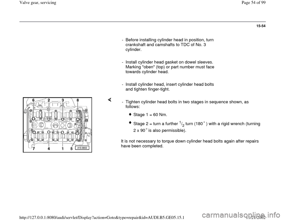
have been completed. - Tighten cylinder head bolts in two stages in sequence shown, as
follows:
Stage 1 = 60 Nm.
Stage 2 = turn a further
1/2 turn (180 ) with a rigid wrench (turning
2 x 90 is also permissible).
Pa
ge 54 of 99 Valve
gear, servicin
g
11/21/2002 htt
p://127.0.0.1:8080/audi/servlet/Dis
play?action=Goto&t
yp
e=re
pair&id=AUDI.B5.GE05.15.1
Page 79 of 99
15-78
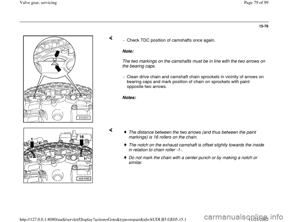
Note:
The two markings on the camshafts must be in line with the two arrows on
the bearing caps.
Notes: - Check TDC position of camshafts once again.
- Clean drive chain and camshaft chain sprockets in vicinity of arrows on
bearing caps and mark position of chain on sprockets with paint
opposite two arrows.
The distance between the two arrows (and thus between the paint
markings) is 16 rollers on the chain. The notch on the exhaust camshaft is offset slightly towards the inside
in relation to chain roller -1-. Do not mark the chain with a center punch or by making a notch or
similar.
Pa
ge 79 of 99 Valve
gear, servicin
g
11/21/2002 htt
p://127.0.0.1:8080/audi/servlet/Dis
play?action=Goto&t
yp
e=re
pair&id=AUDI.B5.GE05.15.1
Page 81 of 99
15-80
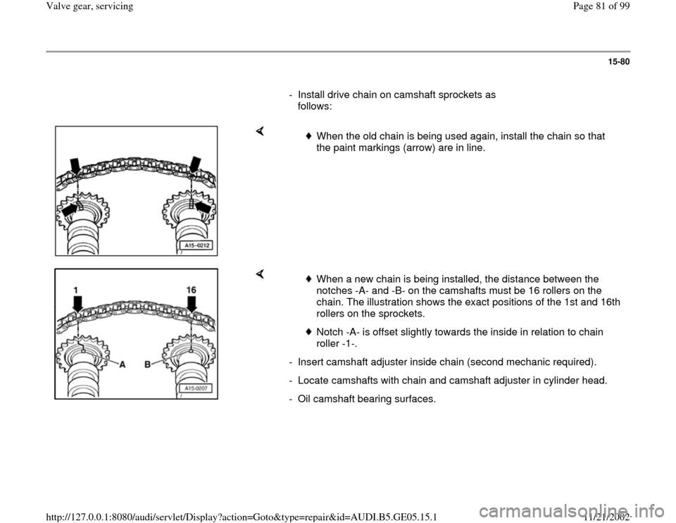
- Install drive chain on camshaft sprockets as
follows:
When the old chain is being used again, install the chain so that
the paint markings (arrow) are in line.
When a new chain is being installed, the distance between the
notches -A- and -B- on the camshafts must be 16 rollers on the
chain. The illustration shows the exact positions of the 1st and 16th
rollers on the sprockets.
Notch -A- is offset slightly towards the inside in relation to chain
roller -1-.
- Insert camshaft adjuster inside chain (second mechanic required).
- Locate camshafts with chain and camshaft adjuster in cylinder head.
- Oil camshaft bearing surfaces.
Pa
ge 81 of 99 Valve
gear, servicin
g
11/21/2002 htt
p://127.0.0.1:8080/audi/servlet/Dis
play?action=Goto&t
yp
e=re
pair&id=AUDI.B5.GE05.15.1
Page 83 of 99
15-82
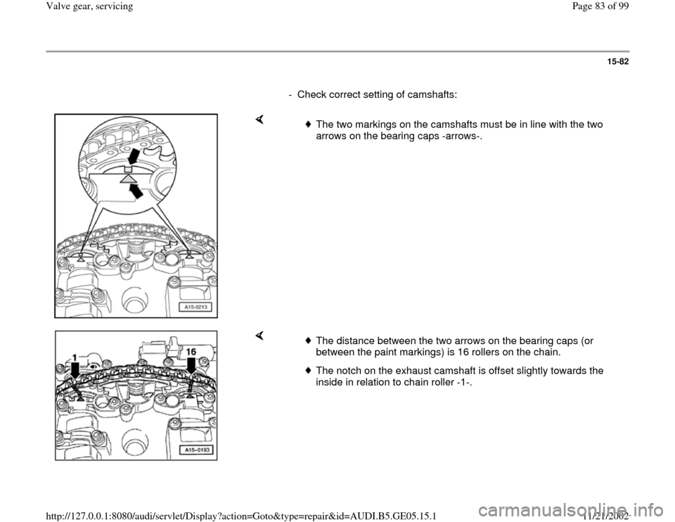
- Check correct setting of camshafts:
The two markings on the camshafts must be in line with the two
arrows on the bearing caps -arrows-.
The distance between the two arrows on the bearing caps (or
between the paint markings) is 16 rollers on the chain.
The notch on the exhaust camshaft is offset slightly towards the
inside in relation to chain roller -1-.
Pa
ge 83 of 99 Valve
gear, servicin
g
11/21/2002 htt
p://127.0.0.1:8080/audi/servlet/Dis
play?action=Goto&t
yp
e=re
pair&id=AUDI.B5.GE05.15.1