sensor AUDI A4 1999 B5 / 1.G Brakes ESP DTC Table Owner's Guide
[x] Cancel search | Manufacturer: AUDI, Model Year: 1999, Model line: A4, Model: AUDI A4 1999 B5 / 1.GPages: 96, PDF Size: 0.3 MB
Page 66 of 96

01-415
Printed output from
VAG1551 Scan Tool
(ST) Possible cause
Corrective action
DTC WARNING!
This is only valid for control modules with no.: 8D0 907 389, 8D0 907 389A, 8D0 907 389D
and 8D0 907 389E.
Continuation:
01425 For control modules 8D0 907 389/A/D/E, the VAG1551 scan tool with test card 8 and the VAG1552
scan tool with test card 5 display the following incorrect text: "Sender for rotation rate -G202-,
reference wire".
Sender for rotation rate
-G202-, signal wire
Failure in electrical
circuit
There is an open circuit in one of the signal
wires for the combined sensor for rotation
rate and transverse acceleration.
There is short circuit to B+ or Ground (GND)
in one of the signal wires for the combined
sensor for rotation rate and transverse
acceleration. Electrical Wiring Diagrams, Troubleshooting &
Component Locations - Check the signal wire for the combined sensor
for rotation rate and transverse acceleration,
terminal 6, to the ABS control module -J104-
(terminal 79).
See continuation on
next page
Sender for rotation rate -G202-
malfunctioning.
Repair Manual, Brake System, Repair Group
45
- If none of the causes listed are causing the
malfunction, replace yaw sensor -G202-.
Pa
ge 66 of 96 Electronic Stabilization Pro
gram
(ESP
) DTC table
11/20/2002 htt
p://127.0.0.1:8080/audi/servlet/Dis
play?action=Goto&t
yp
e=re
pair&id=AUDI.B5.SU02.01.17
Page 67 of 96
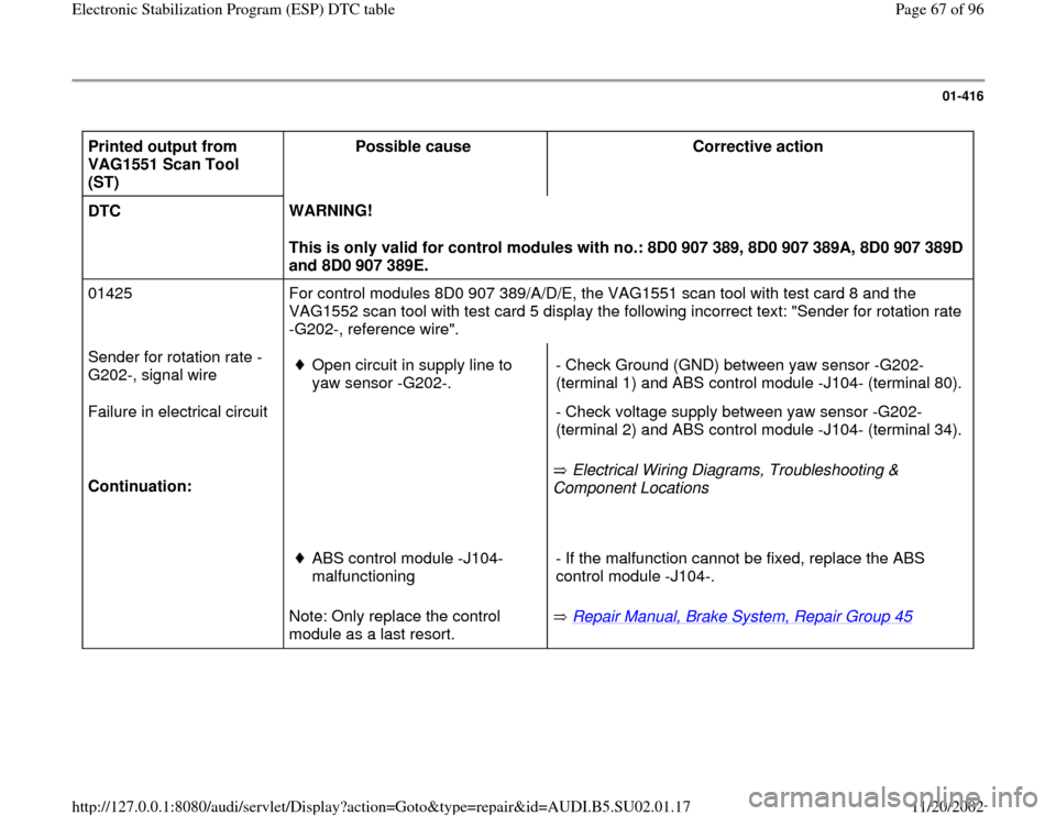
01-416
Printed output from
VAG1551 Scan Tool
(ST) Possible cause
Corrective action
DTC WARNING!
This is only valid for control modules with no.: 8D0 907 389, 8D0 907 389A, 8D0 907 389D
and 8D0 907 389E.
01425 For control modules 8D0 907 389/A/D/E, the VAG1551 scan tool with test card 8 and the
VAG1552 scan tool with test card 5 display the following incorrect text: "Sender for rotation rate
-G202-, reference wire".
Sender for rotation rate -
G202-, signal wire
Failure in electrical circuit
Continuation:
Open circuit in supply line to
yaw sensor -G202-.
Electrical Wiring Diagrams, Troubleshooting &
Component Locations - Check Ground (GND) between yaw sensor -G202-
(terminal 1) and ABS control module -J104- (terminal 80).
- Check voltage supply between yaw sensor -G202-
(terminal 2) and ABS control module -J104- (terminal 34).
Note: Only replace the control
module as a last resort.
ABS control module -J104-
malfunctioning
Repair Manual, Brake System, Repair Group 45
- If the malfunction cannot be fixed, replace the ABS
control module -J104-.
Pa
ge 67 of 96 Electronic Stabilization Pro
gram
(ESP
) DTC table
11/20/2002 htt
p://127.0.0.1:8080/audi/servlet/Dis
play?action=Goto&t
yp
e=re
pair&id=AUDI.B5.SU02.01.17
Page 68 of 96
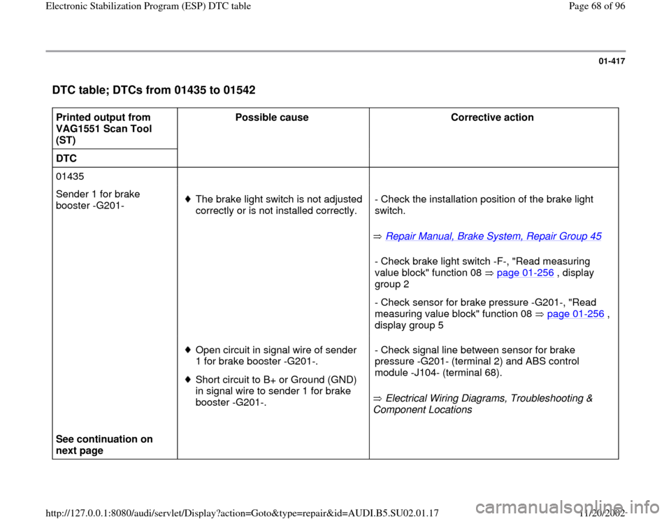
01-417
DTC table; DTCs from 01435 to 01542
Printed output from
VAG1551 Scan Tool
(ST) Possible cause
Corrective action
DTC
01435
Sender 1 for brake
booster -G201-
The brake light switch is not adjusted
correctly or is not installed correctly.
Repair Manual, Brake System, Repair Group 45
- Check the installation position of the brake light
switch.
- Check brake light switch -F-, "Read measuring
value block" function 08 page 01
-256
, display
group 2
- Check sensor for brake pressure -G201-, "Read
measuring value block" function 08 page 01
-256
,
display group 5
See continuation on
next page
Open circuit in signal wire of sender
1 for brake booster -G201-.
Short circuit to B+ or Ground (GND)
in signal wire to sender 1 for brake
booster -G201-. Electrical Wiring Diagrams, Troubleshooting &
Component Locations - Check signal line between sensor for brake
pressure -G201- (terminal 2) and ABS control
module -J104- (terminal 68).
Pa
ge 68 of 96 Electronic Stabilization Pro
gram
(ESP
) DTC table
11/20/2002 htt
p://127.0.0.1:8080/audi/servlet/Dis
play?action=Goto&t
yp
e=re
pair&id=AUDI.B5.SU02.01.17
Page 69 of 96
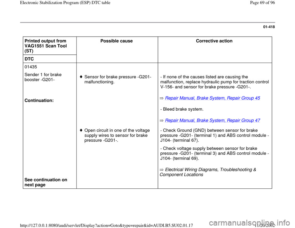
01-418
Printed output from
VAG1551 Scan Tool
(ST) Possible cause
Corrective action
DTC
01435
Sender 1 for brake
booster -G201-
Continuation:
Sensor for brake pressure -G201-
malfunctioning.
Repair Manual, Brake System, Repair Group 45
Repair Manual, Brake System, Repair Group 47 - If none of the causes listed are causing the
malfunction, replace hydraulic pump for traction control
V-156- and sensor for brake pressure -G201-.
- Bleed brake system.
See continuation on
next page
Open circuit in one of the voltage
supply wires to sensor for brake
pressure -G201-.
Electrical Wiring Diagrams, Troubleshooting &
Component Locations - Check Ground (GND) between sensor for brake
pressure -G201- (terminal 1) and ABS control module -
J104- (terminal 67).
- Check voltage supply between sensor for brake
pressure -G201- (terminal 3) and ABS control module -
J104- (terminal 69).
Pa
ge 69 of 96 Electronic Stabilization Pro
gram
(ESP
) DTC table
11/20/2002 htt
p://127.0.0.1:8080/audi/servlet/Dis
play?action=Goto&t
yp
e=re
pair&id=AUDI.B5.SU02.01.17
Page 71 of 96

01-420
Printed output from
VAG1551 Scan Tool
(ST) Possible cause
Corrective action
DTC
01435
Continuation:
Sender 1 for brake booster
-G201-
Failure in electrical circuit
Open circuit in signal wire of sender
1 for brake booster -G201-.
Short circuit to B+ or Ground (GND)
in signal wire to sender 1 for brake
booster -G201-. Electrical Wiring Diagrams, Troubleshooting &
Component Locations - Check signal line between sensor for brake
pressure -G201- (terminal 2) and ABS control
module -J104- (terminal 68).
See continuation on next
page
Open circuit in one of the voltage
supply wires to sensor for brake
pressure -G201-.
Electrical Wiring Diagrams, Troubleshooting &
Component Locations - Check Ground (GND) between sensor for brake
pressure -G201- (terminal 1) and ABS control
module -J104- (terminal 67).
- Check voltage supply between sensor for brake
pressure -G201- (terminal 3) and ABS control
module -J104- (terminal 69).
Pa
ge 71 of 96 Electronic Stabilization Pro
gram
(ESP
) DTC table
11/20/2002 htt
p://127.0.0.1:8080/audi/servlet/Dis
play?action=Goto&t
yp
e=re
pair&id=AUDI.B5.SU02.01.17
Page 72 of 96
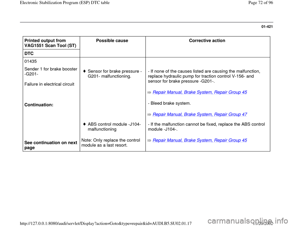
01-421
Printed output from
VAG1551 Scan Tool (ST) Possible cause
Corrective action
DTC
01435
Sender 1 for brake booster
-G201-
Failure in electrical circuit
Continuation:
Sensor for brake pressure -
G201- malfunctioning.
Repair Manual, Brake System, Repair Group 45
Repair Manual, Brake System, Repair Group 47 - If none of the causes listed are causing the malfunction,
replace hydraulic pump for traction control V-156- and
sensor for brake pressure -G201-.
- Bleed brake system.
See continuation on next
page Note: Only replace the control
module as a last resort.
ABS control module -J104-
malfunctioning
Repair Manual, Brake System, Repair Group 45
- If the malfunction cannot be fixed, replace the ABS control
module -J104-. Pa
ge 72 of 96 Electronic Stabilization Pro
gram
(ESP
) DTC table
11/20/2002 htt
p://127.0.0.1:8080/audi/servlet/Dis
play?action=Goto&t
yp
e=re
pair&id=AUDI.B5.SU02.01.17
Page 73 of 96
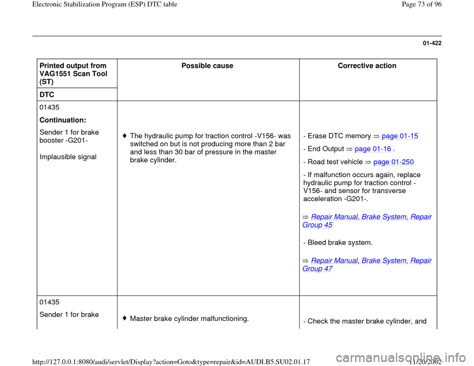
01-422
Printed output from
VAG1551 Scan Tool
(ST) Possible cause
Corrective action
DTC
01435
Continuation:
Sender 1 for brake
booster -G201-
Implausible signal
The hydraulic pump for traction control -V156- was
switched on but is not producing more than 2 bar
and less than 30 bar of pressure in the master
brake cylinder.
Repair Manual, Brake System, Repair
Group 45
Repair Manual, Brake System, Repair
Group 47
- Erase DTC memory page 01
-15
- End Output page 01
-16
.
- Road test vehicle page 01
-250
- If malfunction occurs again, replace
hydraulic pump for traction control -
V156- and sensor for transverse
acceleration -G201-. - Bleed brake system.
01435
Sender 1 for brake
Master brake cylinder malfunctioning.
- Check the master brake cylinder, and
Pa
ge 73 of 96 Electronic Stabilization Pro
gram
(ESP
) DTC table
11/20/2002 htt
p://127.0.0.1:8080/audi/servlet/Dis
play?action=Goto&t
yp
e=re
pair&id=AUDI.B5.SU02.01.17
Page 75 of 96

01-423
Printed output from
VAG1551 Scan Tool (ST) Possible cause
Corrective action
DTC
01435
Continuation:
Sender 1 for brake booster
-G201-
- voltage supply
Voltage supply has a short circuit
to B+.
Voltage supply has a short circuit
to Ground (GND).
Open circuit in one of the voltage
supply wires to sensor for brake
pressure -G201-.
Electrical Wiring Diagrams, Troubleshooting &
Component Locations - Check Ground (GND) between sensor for brake
pressure -G201- (terminal 1) and ABS control module
-J104- (terminal 67).
- Check voltage supply between sensor for brake
pressure -G201- (terminal 3) and ABS control module
-J104- (terminal 69).
Pa
ge 75 of 96 Electronic Stabilization Pro
gram
(ESP
) DTC table
11/20/2002 htt
p://127.0.0.1:8080/audi/servlet/Dis
play?action=Goto&t
yp
e=re
pair&id=AUDI.B5.SU02.01.17
Page 76 of 96
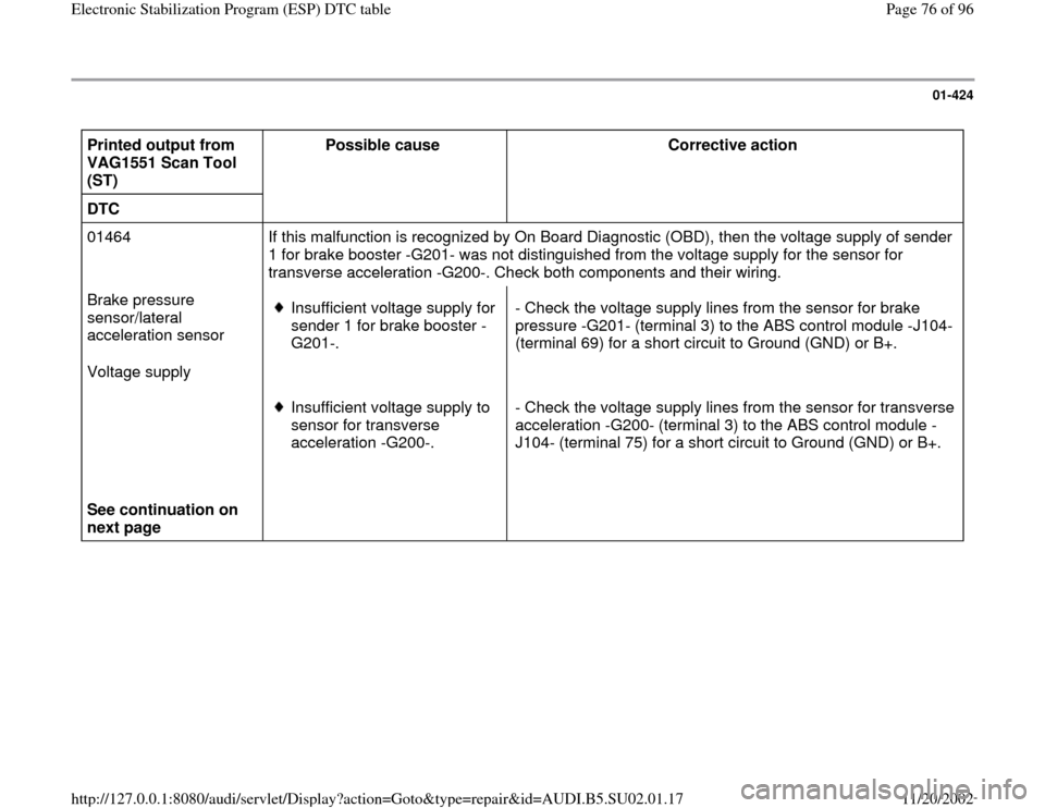
01-424
Printed output from
VAG1551 Scan Tool
(ST) Possible cause
Corrective action
DTC
01464 If this malfunction is recognized by On Board Diagnostic (OBD), then the voltage supply of sender
1 for brake booster -G201- was not distinguished from the voltage supply for the sensor for
transverse acceleration -G200-. Check both components and their wiring.
Brake pressure
sensor/lateral
acceleration sensor
Voltage supply
Insufficient voltage supply for
sender 1 for brake booster -
G201-. - Check the voltage supply lines from the sensor for brake
pressure -G201- (terminal 3) to the ABS control module -J104-
(terminal 69) for a short circuit to Ground (GND) or B+.
See continuation on
next page Insufficient voltage supply to
sensor for transverse
acceleration -G200-. - Check the voltage supply lines from the sensor for transverse
acceleration -G200- (terminal 3) to the ABS control module -
J104- (terminal 75) for a short circuit to Ground (GND) or B+.
Pa
ge 76 of 96 Electronic Stabilization Pro
gram
(ESP
) DTC table
11/20/2002 htt
p://127.0.0.1:8080/audi/servlet/Dis
play?action=Goto&t
yp
e=re
pair&id=AUDI.B5.SU02.01.17
Page 77 of 96
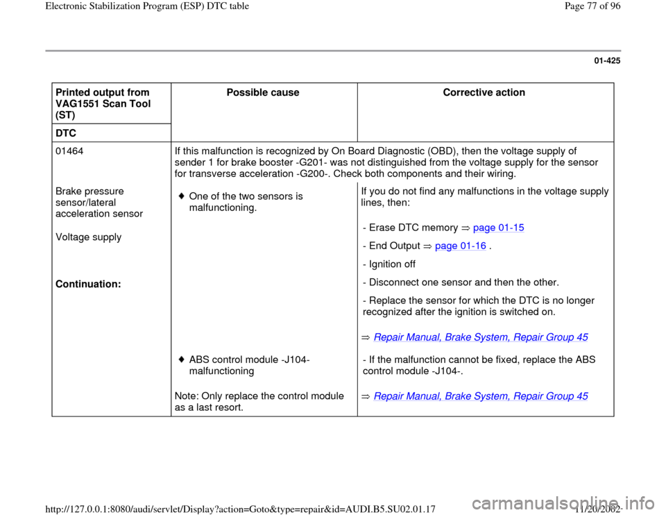
01-425
Printed output from
VAG1551 Scan Tool
(ST) Possible cause
Corrective action
DTC
01464 If this malfunction is recognized by On Board Diagnostic (OBD), then the voltage supply of
sender 1 for brake booster -G201- was not distinguished from the voltage supply for the sensor
for transverse acceleration -G200-. Check both components and their wiring.
Brake pressure
sensor/lateral
acceleration sensor
Voltage supply
Continuation:
One of the two sensors is
malfunctioning. If you do not find any malfunctions in the voltage supply
lines, then:
Repair Manual, Brake System, Repair Group 45
- Erase DTC memory page 01
-15
- End Output page 01
-16
.
- Ignition off
- Disconnect one sensor and then the other.
- Replace the sensor for which the DTC is no longer
recognized after the ignition is switched on.
Note: Only replace the control module
as a last resort.
ABS control module -J104-
malfunctioning
Repair Manual, Brake System, Repair Group 45
- If the malfunction cannot be fixed, replace the ABS
control module -J104-.
Pa
ge 77 of 96 Electronic Stabilization Pro
gram
(ESP
) DTC table
11/20/2002 htt
p://127.0.0.1:8080/audi/servlet/Dis
play?action=Goto&t
yp
e=re
pair&id=AUDI.B5.SU02.01.17