diagram AUDI A4 2000 B5 / 1.G 01V Transmission Electrical Testing User Guide
[x] Cancel search | Manufacturer: AUDI, Model Year: 2000, Model line: A4, Model: AUDI A4 2000 B5 / 1.GPages: 66, PDF Size: 0.28 MB
Page 23 of 66
01-288
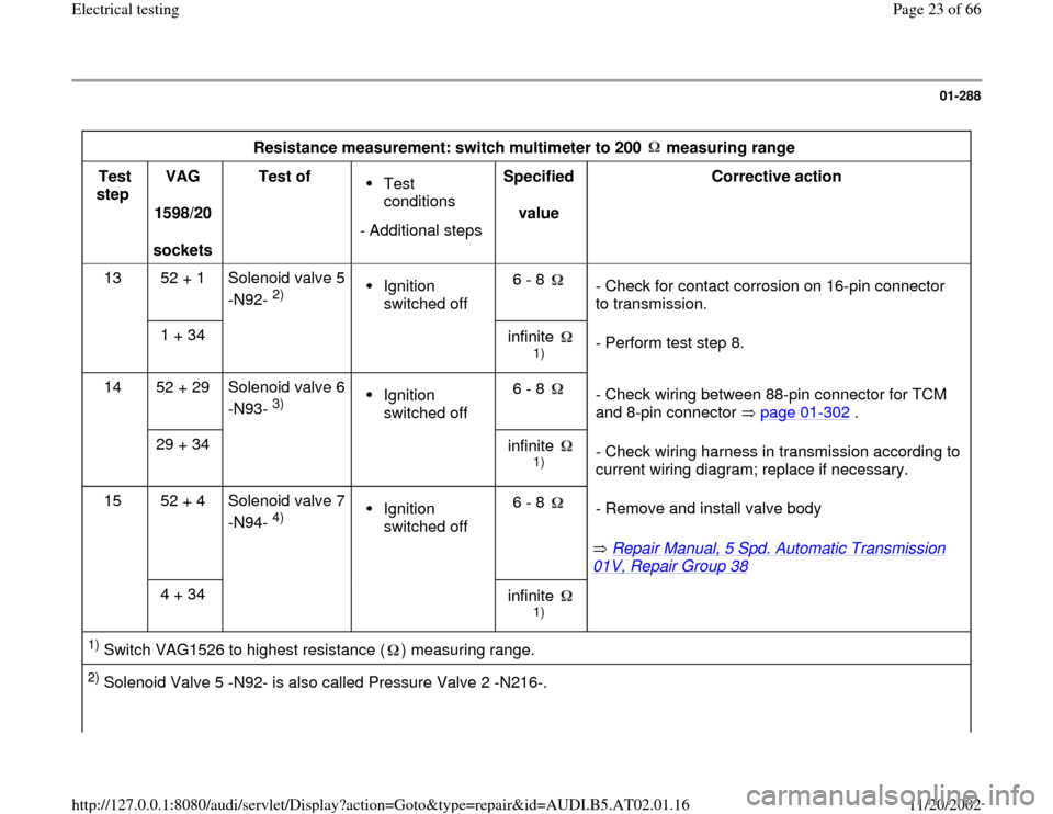
Resistance measurement: switch multimeter to 200 measuring range
Test
step VAG
1598/20
sockets Test of
Test
conditions
- Additional stepsSpecified
value Corrective action
13 52 + 1 Solenoid valve 5
-N92-
2)
Ignition
switched off 6 - 8
- Check for contact corrosion on 16-pin connector
to transmission.
1 + 34
infinite
1)
- Perform test step 8.
14 52 + 29 Solenoid valve 6
-N93-
3)
Ignition
switched off 6 - 8
- Check wiring between 88-pin connector for TCM
and 8-pin connector page 01
-302
.
29 + 34
infinite
1)
- Check wiring harness in transmission according to
current wiring diagram; replace if necessary.
15 52 + 4 Solenoid valve 7
-N94-
4)
Ignition
switched off 6 - 8
Repair Manual, 5 Spd. Automatic Transmission
01V, Repair Group 38
- Remove and install valve body
4 + 34
infinite
1)
1) Switch VAG1526 to highest resistance ( ) measuring range. 2) Solenoid Valve 5 -N92- is also called Pressure Valve 2 -N216-.
Pa
ge 23 of 66 Electrical testin
g
11/20/2002 htt
p://127.0.0.1:8080/audi/servlet/Dis
play?action=Goto&t
yp
e=re
pair&id=AUDI.B5.AT02.01.16
Page 25 of 66
01-289
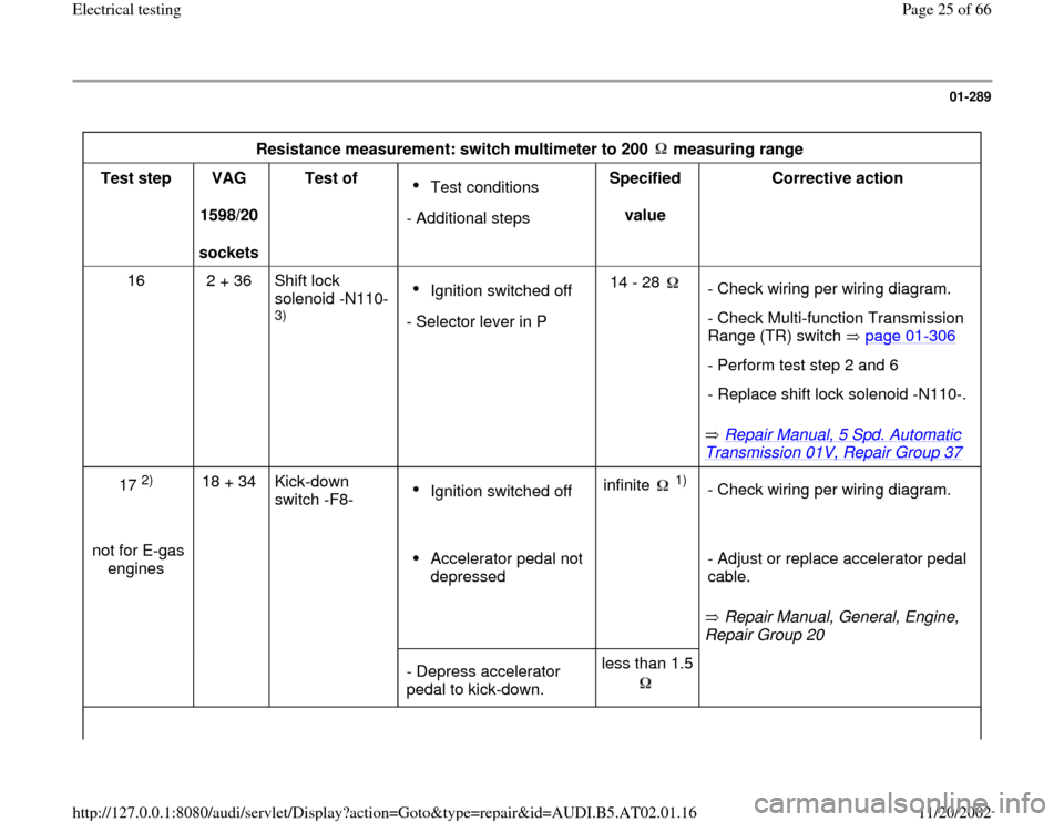
Resistance measurement: switch multimeter to 200 measuring range
Test step
VAG
1598/20
sockets Test of
Test conditions
- Additional stepsSpecified
value Corrective action
16 2 + 36 Shift lock
solenoid -N110-
3)
Ignition switched off
- Selector lever in P14 - 28
Repair Manual, 5 Spd. Automatic
Transmission 01V, Repair Group 37
- Check wiring per wiring diagram.
- Check Multi-function Transmission
Range (TR) switch page 01
-306
- Perform test step 2 and 6
- Replace shift lock solenoid -N110-.
17
2)
18 + 34 Kick-down
switch -F8-
Ignition switched off infinite
1)
- Check wiring per wiring diagram.
not for E-gas
engines
Accelerator pedal not
depressed
Repair Manual, General, Engine,
Repair Group 20 - Adjust or replace accelerator pedal
cable.
- Depress accelerator
pedal to kick-down. less than 1.5
Pa
ge 25 of 66 Electrical testin
g
11/20/2002 htt
p://127.0.0.1:8080/audi/servlet/Dis
play?action=Goto&t
yp
e=re
pair&id=AUDI.B5.AT02.01.16
Page 27 of 66
01-290
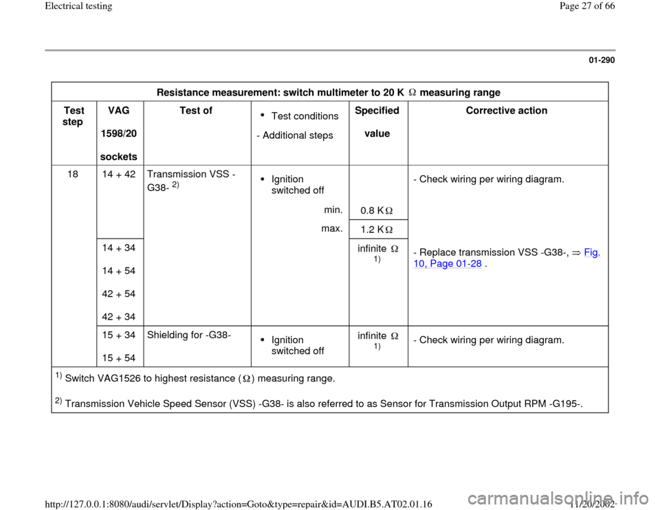
Resistance measurement: switch multimeter to 20 K measuring range
Test
step VAG
1598/20
sockets Test of
Test conditions
- Additional stepsSpecified
value Corrective action
18 14 + 42 Transmission VSS -
G38-
2)
Ignition
switched off
- Check wiring per wiring diagram.
min.
0.8 K
max.
1.2 K
14 + 34
14 + 54
42 + 54
42 + 34
infinite
1)
- Replace transmission VSS -G38-, Fig. 10, Page 01
-28
.
15 + 34
15 + 54 Shielding for -G38-
Ignition
switched off infinite
1)
- Check wiring per wiring diagram.
1) Switch VAG1526 to highest resistance ( ) measuring range. 2) Transmission Vehicle Speed Sensor (VSS) -G38- is also referred to as Sensor for Transmission Output RPM -G195-.
Pa
ge 27 of 66 Electrical testin
g
11/20/2002 htt
p://127.0.0.1:8080/audi/servlet/Dis
play?action=Goto&t
yp
e=re
pair&id=AUDI.B5.AT02.01.16
Page 28 of 66
01-291
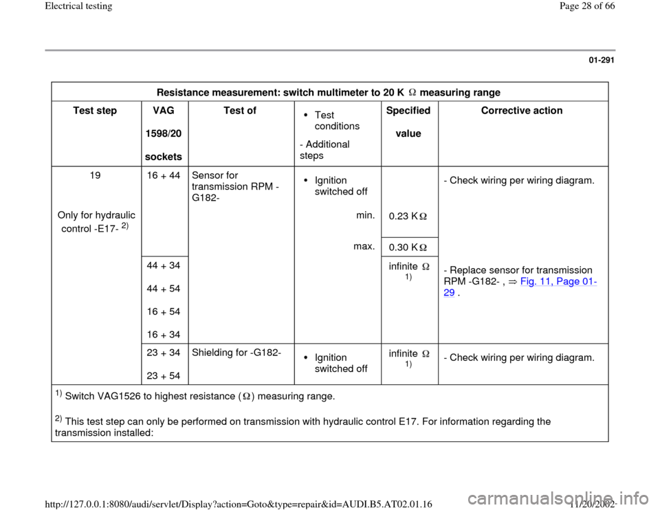
Resistance measurement: switch multimeter to 20 K measuring range
Test step
VAG
1598/20
sockets Test of
Test
conditions
- Additional
steps Specified
value Corrective action
19 16 + 44 Sensor for
transmission RPM -
G182- Ignition
switched off
- Check wiring per wiring diagram.
Only for hydraulic
control -E17-
2) min.
0.23 K
max.
0.30 K
44 + 34
44 + 54
16 + 54
16 + 34
infinite
1)
- Replace sensor for transmission
RPM -G182- , Fig. 11, Page 01
-
29
.
23 + 34
23 + 54 Shielding for -G182-
Ignition
switched off infinite
1)
- Check wiring per wiring diagram.
1) Switch VAG1526 to highest resistance ( ) measuring range. 2) This test step can only be performed on transmission with hydraulic control E17. For information regarding the
transmission installed:
Pa
ge 28 of 66 Electrical testin
g
11/20/2002 htt
p://127.0.0.1:8080/audi/servlet/Dis
play?action=Goto&t
yp
e=re
pair&id=AUDI.B5.AT02.01.16
Page 32 of 66
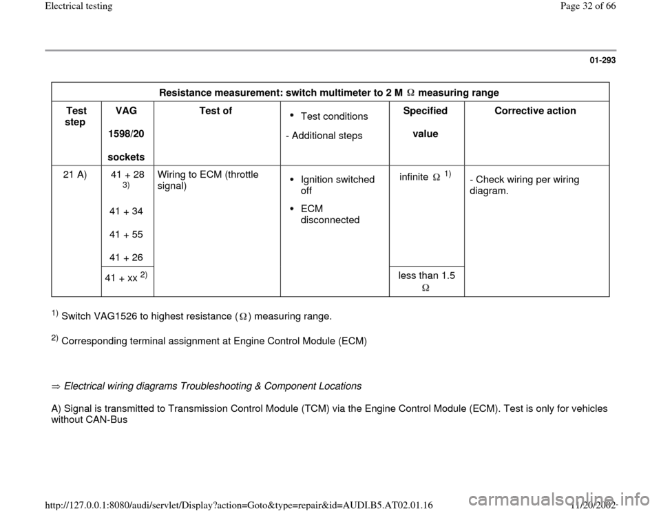
01-293
Resistance measurement: switch multimeter to 2 M measuring range
Test
step VAG
1598/20
sockets Test of
Test conditions
- Additional stepsSpecified
value Corrective action
21 A) 41 + 28
3)
41 + 34
41 + 55
41 + 26 Wiring to ECM (throttle
signal)
Ignition switched
off ECM
disconnected infinite
1)
- Check wiring per wiring
diagram.
41 + xx
2)
less than 1.5
1) Switch VAG1526 to highest resistance ( ) measuring range. 2) Corresponding terminal assignment at Engine Control Module (ECM)
Electrical wiring diagrams Troubleshooting & Component Locations A) Signal is transmitted to Transmission Control Module (TCM) via the Engine Control Module (ECM). Test is only for vehicles
without CAN-Bus
Pa
ge 32 of 66 Electrical testin
g
11/20/2002 htt
p://127.0.0.1:8080/audi/servlet/Dis
play?action=Goto&t
yp
e=re
pair&id=AUDI.B5.AT02.01.16
Page 34 of 66
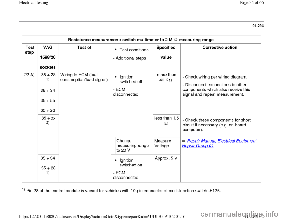
01-294
Resistance measurement: switch multimeter to 2 M measuring range
Test
step VAG
1598/20
sockets Test of
Test conditions
- Additional stepsSpecified
value Corrective action
22 A) 35 + 28
1)
35 + 34
35 + 55
35 + 26 Wiring to ECM (fuel
consumption/load signal)
Ignition
switched off
- ECM
disconnected more than
40 K
- Check wiring per wiring diagram.
- Disconnect connections to other
components which also receive this
signal and repeat measurement.
35 + xx
2)
less than 1.5
- Check these components for short
circuit if necessary (e.g. on-board
computer).
Change
measuring range
to 20 V Measure
Voltage Repair Manual, Electrical Equipment, Repair Group 01
35 + 34
35 + 28
1)
Ignition
switched on
- ECM
disconnected Approx. 5 V
1) Pin 28 at the control module is vacant for vehicles with 10-pin connector of multi-function switch -F125-.
Pa
ge 34 of 66 Electrical testin
g
11/20/2002 htt
p://127.0.0.1:8080/audi/servlet/Dis
play?action=Goto&t
yp
e=re
pair&id=AUDI.B5.AT02.01.16
Page 35 of 66
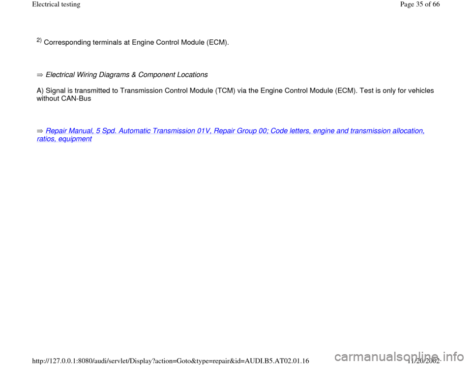
2) Corresponding terminals at Engine Control Module (ECM).
Electrical Wiring Diagrams & Component Locations A) Signal is transmitted to Transmission Control Module (TCM) via the Engine Control Module (ECM). Test is only for vehicles
without CAN-Bus
Repair Manual, 5 Spd. Automatic Transmission 01V, Repair Group 00; Code letters, engine and transmission allocation, ratios, equipment
Pa
ge 35 of 66 Electrical testin
g
11/20/2002 htt
p://127.0.0.1:8080/audi/servlet/Dis
play?action=Goto&t
yp
e=re
pair&id=AUDI.B5.AT02.01.16
Page 36 of 66
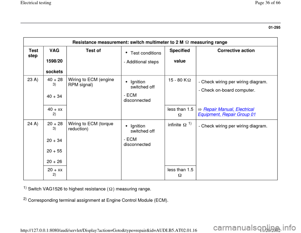
01-295
Resistance measurement: switch multimeter to 2 M measuring range
Test
step VAG
1598/20
sockets Test of
Test conditions
- Additional stepsSpecified
value Corrective action
23 A) 40 + 28
3)
40 + 34 Wiring to ECM (engine
RPM signal)
Ignition
switched off
- ECM
disconnected 15 - 80 K
- Check wiring per wiring diagram.
- Check on-board computer.
40 + xx
2)
less than 1.5
Repair Manual, Electrical
Equipment, Repair Group 01
24 A) 20 + 28
3)
20 + 34
20 + 55
20 + 26 Wiring to ECM (torque
reduction)
Ignition
switched off
- ECM
disconnected infinite
1)
- Check wiring per wiring diagram.
20 + xx
2)
less than 1.5
1) Switch VAG1526 to highest resistance ( ) measuring range. 2) Corresponding terminal assignment at Engine Control Module (ECM).
Pa
ge 36 of 66 Electrical testin
g
11/20/2002 htt
p://127.0.0.1:8080/audi/servlet/Dis
play?action=Goto&t
yp
e=re
pair&id=AUDI.B5.AT02.01.16
Page 37 of 66
Electrical Wiring Diagrams & Component Locations binder A) Signal is transmitted to Transmission Control Module (TCM) via the Engine Control Module (ECM). Test is only for vehicles
without CAN-Bus
Repair Manual, 5 Spd. Automatic Transmission 01V, Repair Group 00; Code letters, aggregate allocation, ratios, equipment
3) Pin 28 at the control module is vacant for vehicles with 10-pin connector of multi-function switch -F125-.
Pa
ge 37 of 66 Electrical testin
g
11/20/2002 htt
p://127.0.0.1:8080/audi/servlet/Dis
play?action=Goto&t
yp
e=re
pair&id=AUDI.B5.AT02.01.16
Page 38 of 66
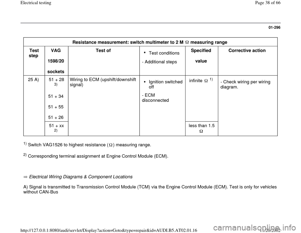
01-296
Resistance measurement: switch multimeter to 2 M measuring range
Test
step VAG
1598/20
sockets Test of
Test conditions
- Additional steps Specified
value Corrective action
25 A) 51 + 28
3)
51 + 34
51 + 55
51 + 26 Wiring to ECM (upshift/downshift
signal)
Ignition switched
off
- ECM
disconnected infinite
1)
- Check wiring per wiring
diagram.
51 + xx
2)
less than 1.5
1) Switch VAG1526 to highest resistance ( ) measuring range. 2) Corresponding terminal assignment at Engine Control Module (ECM).
Electrical Wiring Diagrams & Component Locations A) Signal is transmitted to Transmission Control Module (TCM) via the Engine Control Module (ECM). Test is only for vehicles
without CAN-Bus
Pa
ge 38 of 66 Electrical testin
g
11/20/2002 htt
p://127.0.0.1:8080/audi/servlet/Dis
play?action=Goto&t
yp
e=re
pair&id=AUDI.B5.AT02.01.16