AUDI A4 2000 B5 / 1.G APB Engine Exhaust System Components User Guide
Manufacturer: AUDI, Model Year: 2000, Model line: A4, Model: AUDI A4 2000 B5 / 1.GPages: 30, PDF Size: 0.58 MB
Page 11 of 30
26-11
Exhaust system, aligning free of stress
Align the exhaust system as follows to avoid
stresses in the system and prevent the
transmission of noise into the body:
Notes:
Before assembling the exhaust system, the
front exhaust pipes and the catalytic converters
must be aligned accurately and secured.
Loosen all bolted connections on the exhaust
system (except exhaust manifold and flange
mountings, catalytic converter/intermediate
pipe).
The exhaust system must be aligned when it is
cold.
Keep to the sequence described below.
The dimensions in the illustrations are
approximate.
Pa
ge 11 of 30 Exhaust s
ystem com
ponents, removin
g and installin
g
11/21/2002 htt
p://127.0.0.1:8080/audi/servlet/Dis
play?action=Goto&t
yp
e=re
pair&id=AUDI.B5.GE05.26.1
Page 12 of 30
26-12
Vehicles without clamp between center and
rear muffler
- Loosen screws of front clamp between catalytic
converter and center muffler.
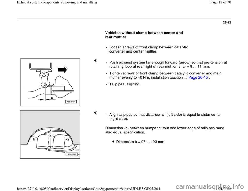
- Push exhaust system far enough forward (arrow) so that pre-tension at
retaining loop at rear right of rear muffler is -a- = 9 ... 11 mm.
- Tighten screws of front clamp between catalytic converter and main
muffler evenly to 40 Nm, installation position Page 26
-15
.
- Tailpipes, aligning
Dimension -b- between bumper cutout and lower edge of tailpipes must
also equal specification. - Align tailpipes so that distance -a- (left side) is equal to distance -a-
(right side).
Dimension b = 97 ... 103 mm
Pa
ge 12 of 30 Exhaust s
ystem com
ponents, removin
g and installin
g
11/21/2002 htt
p://127.0.0.1:8080/audi/servlet/Dis
play?action=Goto&t
yp
e=re
pair&id=AUDI.B5.GE05.26.1
Page 13 of 30
26-13
Vehicles with clamp between front muffler
and rear muffler
Note:
It is only necessary to additionally align the front
muffler on vehicles with clamp fitted between
front muffler and rear muffler.
- Loosen bolted connections on front clamps
between catalytic converters and front muffler.
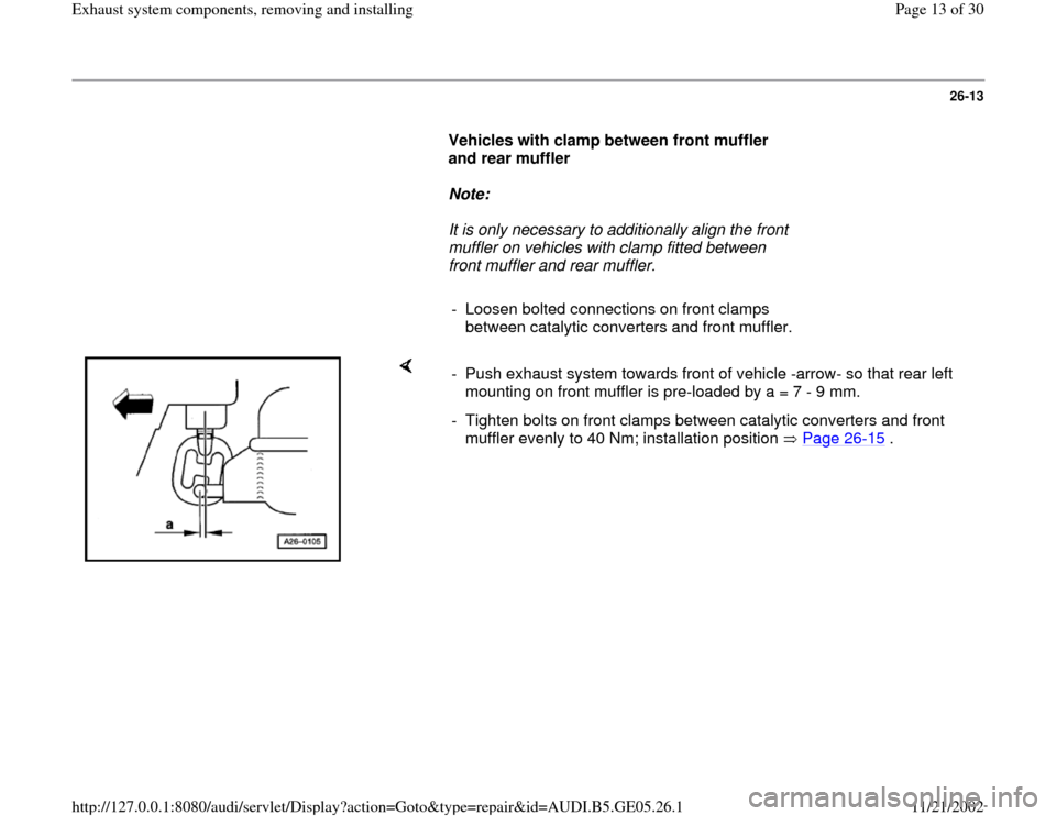
- Push exhaust system towards front of vehicle -arrow- so that rear left
mounting on front muffler is pre-loaded by a = 7 - 9 mm.
- Tighten bolts on front clamps between catalytic converters and front
muffler evenly to 40 Nm; installation position Page 26
-15
. Pa
ge 13 of 30 Exhaust s
ystem com
ponents, removin
g and installin
g
11/21/2002 htt
p://127.0.0.1:8080/audi/servlet/Dis
play?action=Goto&t
yp
e=re
pair&id=AUDI.B5.GE05.26.1
Page 14 of 30
26-14
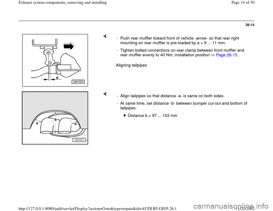
Aligning tailpipes - Push rear muffler toward front of vehicle -arrow- so that rear right
mounting on rear muffler is pre-loaded by a = 9 ... 11 mm.
- Tighten bolted connections on rear clamp between front muffler and
rear muffler evenly to 40 Nm; installation position Page 26
-15
.
- Align tailpipes so that distance -a- is same on both sides.
- At same time, set distance -b- between bumper cut-out and bottom of
tailpipes:
Distance b = 97 ... 103 mm
Pa
ge 14 of 30 Exhaust s
ystem com
ponents, removin
g and installin
g
11/21/2002 htt
p://127.0.0.1:8080/audi/servlet/Dis
play?action=Goto&t
yp
e=re
pair&id=AUDI.B5.GE05.26.1
Page 15 of 30
26-15
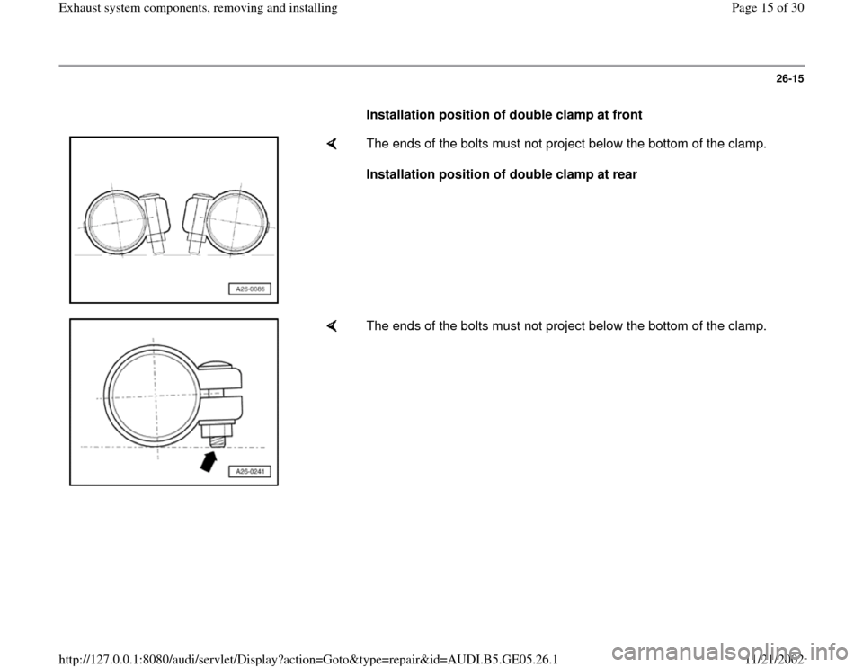
Installation position of double clamp at front
The ends of the bolts must not project below the bottom of the clamp.
Installation position of double clamp at rear
The ends of the bolts must not project below the bottom of the clamp.
Pa
ge 15 of 30 Exhaust s
ystem com
ponents, removin
g and installin
g
11/21/2002 htt
p://127.0.0.1:8080/audi/servlet/Dis
play?action=Goto&t
yp
e=re
pair&id=AUDI.B5.GE05.26.1
Page 16 of 30
26-16
Exhaust system, checking for leaks
- Start engine and run at idling speed.
- Plug tailpipe (e. g. with rag or stopper) and leave
plugged until check is complete.
- Listen for noise at connection points (cylinder
head/manifold, manifold/turbocharger,
turbocharger/catalytic converter, etc.) to locate
leaks.
- Correct any leaks that are found.
Pa
ge 16 of 30 Exhaust s
ystem com
ponents, removin
g and installin
g
11/21/2002 htt
p://127.0.0.1:8080/audi/servlet/Dis
play?action=Goto&t
yp
e=re
pair&id=AUDI.B5.GE05.26.1
Page 17 of 30
26-17
Exhaust manifold, removing and
installing
Removing
- Remove engine Page 10
-1 .
- Remove turbocharger Page 21
-1
- Unbolt exhaust manifold.
Installing
Notes:
Replace self-locking nuts.
Replace gaskets.
- Install in reverse sequence.
Pa
ge 17 of 30 Exhaust s
ystem com
ponents, removin
g and installin
g
11/21/2002 htt
p://127.0.0.1:8080/audi/servlet/Dis
play?action=Goto&t
yp
e=re
pair&id=AUDI.B5.GE05.26.1
Page 18 of 30
26-18
Tightening torques
Bolted mountings Tightening
torques
Exhaust pipe between exhaust
manifold and turbocharger 25 Nm
Exhaust pipe with catalytic
converter to turbocharger 25 Nm
Exhaust manifold to cylinder
head 25 Nm
Exhaust pipe to transmission 25 Nm
Catalytic converter to front
muffler 25 Nm
Heat shield to turbocharger 10 Nm
Pa
ge 18 of 30 Exhaust s
ystem com
ponents, removin
g and installin
g
11/21/2002 htt
p://127.0.0.1:8080/audi/servlet/Dis
play?action=Goto&t
yp
e=re
pair&id=AUDI.B5.GE05.26.1
Page 19 of 30
26-19
Exhaust gas temperature sensor,
checking for function
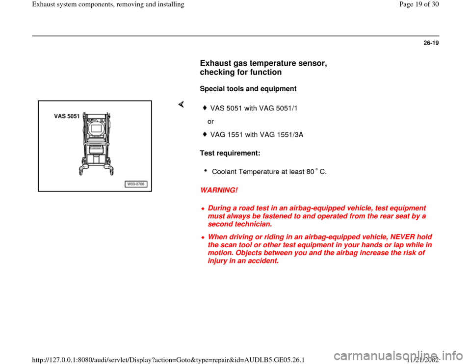
Special tools and equipment
Test requirement:
WARNING!
VAS 5051 with VAG 5051/1
orVAG 1551 with VAG 1551/3ACoolant Temperature at least 80 C. During a road test in an airbag-equipped vehicle, test equipment
must always be fastened to and operated from the rear seat by a
second technician. When driving or riding in an airbag-equipped vehicle, NEVER hold
the scan tool or other test equipment in your hands or lap while in
motion. Objects between you and the airbag increase the risk of
injury in an accident.
Pa
ge 19 of 30 Exhaust s
ystem com
ponents, removin
g and installin
g
11/21/2002 htt
p://127.0.0.1:8080/audi/servlet/Dis
play?action=Goto&t
yp
e=re
pair&id=AUDI.B5.GE05.26.1
Page 20 of 30
26-20
Test sequence
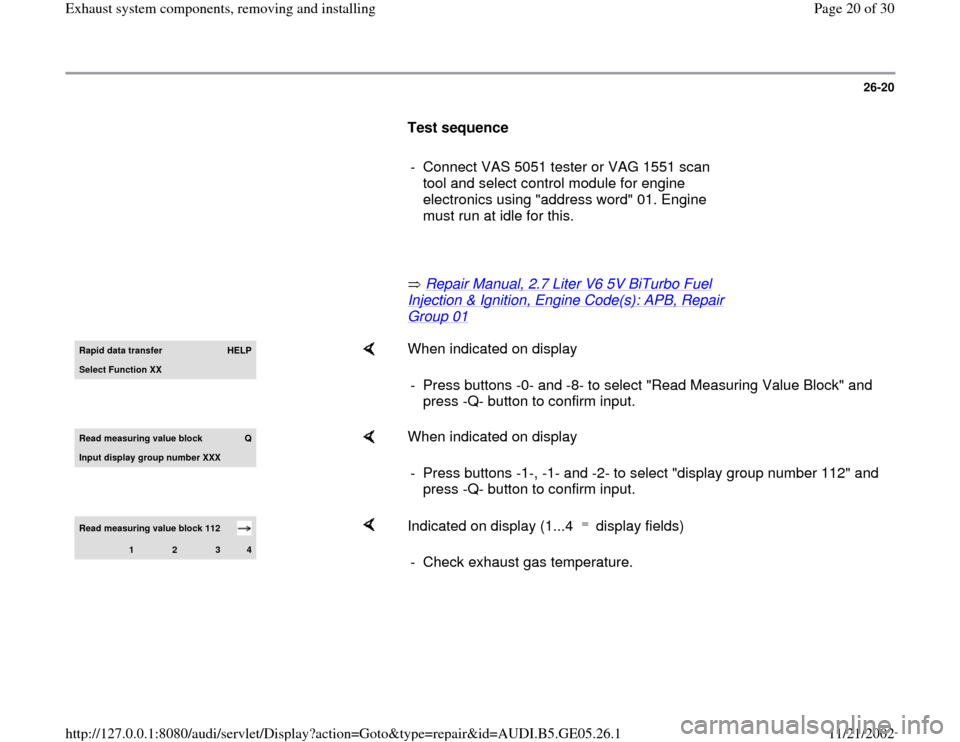
- Connect VAS 5051 tester or VAG 1551 scan
tool and select control module for engine
electronics using "address word" 01. Engine
must run at idle for this.
Repair Manual, 2.7 Liter V6 5V BiTurbo Fuel
Injection & Ignition, Engine Code(s): APB, Repair Group 01
Rapid data transfer
HELP
Select Function XX
When indicated on display
- Press buttons -0- and -8- to select "Read Measuring Value Block" and
press -Q- button to confirm input.
Read measurin
g value block
Q
Input display group number XXX
When indicated on display
- Press buttons -1-, -1- and -2- to select "display group number 112" and
press -Q- button to confirm input.
Read measuring value block 112
1
2
3
4
Indicated on display (1...4 display fields) - Check exhaust gas temperature.
Pa
ge 20 of 30 Exhaust s
ystem com
ponents, removin
g and installin
g
11/21/2002 htt
p://127.0.0.1:8080/audi/servlet/Dis
play?action=Goto&t
yp
e=re
pair&id=AUDI.B5.GE05.26.1